



Flotide/MEGA Pool Pump, Spv 150 exploded view & spare parts
 Certified online store
 Easy returns within 14 days


Spare parts list

Flotide/MEGA - Pre-filter Lid Nut for SPV 150 Pool Pump - 7029246
€21,95
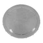
Flotide/MEGA - Transparent Pre-filter Lid for SPV 150 Pump - 7029247
€23,45

Flotide/MEGA - Pre-filter Lid O-Ring for SPV 150 Pump - 7029248
€6,95

Flotide/MEGA - Pump Strainer Basket for SPV 150 - 7029249
€15,95

Flotide/MEGA - Pool Pump Union with Nut 50mm / 1½" Glue Socket, Black - 7029276
€31,45

Flotide/MEGA - Pump Body for SPV 150 - 7029250
€221,45

Flotide/MEGA - Diffuser O-Ring for SPV 150 Pool Pump - 7029251
€6,95

Flotide/MEGA - Pump Diffuser for SPV 150 - 7029252
€23,45

Flotide/MEGA - Impeller Screw with O-Ring for SPV 150 - 7029253
€8,95

Flotide/MEGA - Replacement Impeller for SPV 150 Variable Speed Pool Pump - 7029254
€52,45

Flotide/MEGA - Mechanical Seal 3/4" for SC / SB / SPV Pool Pumps - 7029255
€55,95

Flotide/MEGA - Flange O-Ring for SPV 150 Pool Pump - 7029256
€10,45

Flotide/MEGA - Pump Body Flange for SPV 150 - 7029257
€69,95

Flotide/MEGA - Replacement Motor for SPV 150 Variable Speed Pool Pump (TYC-71L) - 7029258
€630,45

Flotide/MEGA - Motor Cooling Fan for SS/SD/SQ/ST/SPV Pool Pumps (050–120) - 7009302
€5,45

Flotide/MEGA - Motor Fan Cover for SPV 150 Variable Speed Pool Pump - 7029259
€12,45

Flotide/MEGA - Programmable Controller for SPV 150 Variable Speed Pump (Without Plug) - 7029260
€565,95

Flotide/MEGA - Controller Transparent Lid for SPV 150 Pool Pump - 7029261
€6,95

Description
Flotide/MEGA Pool Pump SPV 150 exploded view & spare parts
This page covers the complete exploded-view diagram and full bill of materials for the Flotide/MEGA Super-Power variable speed pool pump, model SPV 150. The SPV 150 is a 1.1 kW variable speed pump with a 1½" union connection, designed to reduce running costs through programmable speed schedules. No parent factory reference numbers are registered for this model, so the diagram position numbers and SKUs shown below are the definitive way to identify each component. Work through the numbered diagram and you will have the correct part reference in minutes.
How to use the numbered diagram to find your part
Every numbered call-out on the diagram corresponds directly to a row in the parts list beneath it — locate the area of the pump where you can see the worn or damaged component, find its call-out number on the diagram, then match that number to the same position in the table to retrieve the SKU. Add the SKU to your basket or use it to search the site for the exact listing. Bear in mind that a single position number can appear more than once on the diagram where an identical part is used in several locations — the screw positions 15 and 16 are a good example, as both types of motor screw may appear at multiple fixing points around the motor flange. Position 18 is shared by two distinct parts — the base itself and the arch cushion that fits beneath it — so read the description column carefully rather than relying on the number alone. Where a position carries a letter suffix (21a, 21b, 21c), each letter denotes a genuinely different variant, not simply a duplicate; choosing the wrong letter will result in an incompatible part. Finally, note that some positions in this diagram do not yet carry a listed SKU — positions 7, 15, 16, 18 (both entries), and 21b and 21c fall into this category — so please contact us directly if you need any of those items.
Main replaceable assemblies on the Flotide/MEGA SPV 150
The pump is built around a wet-end assembly and a motor assembly joined at a central flange. The wet end begins at the top with the transparent strainer lid (position 2), which is retained by a large hand-tightened nut (position 1) and sealed with a dedicated O-ring (position 3, SKU 7029248) — this lid O-ring is one of the most frequently replaced consumables on the pump. Beneath the lid sits the basket (position 4, SKU 7029249), which collects debris before water reaches the impeller. Water enters and leaves the pump body (position 6, SKU 7029250) via the 1½" unions (position 5, SKU 7029276), and any residual water in the body is drained through the drain plug with its integrated O-ring (position 7). Inside the wet end, the diffuser (position 9, SKU 7029252) is sealed by its own O-ring (position 8, SKU 7029251) and guides flow around the impeller (position 11, SKU 7029254), which is locked to the motor shaft by a dedicated screw with O-ring (position 10, SKU 7029253). The mechanical seal (position 12, SKU 7029255) is the critical water-tight barrier between the wet end and the motor; it is rated at ¾" for the SPV series and should be renewed whenever any shaft-side leakage is detected. The motor assembly (position 17, SKU 7029258, motor type TYC-71L) is bolted to the wet end through the flange (position 14, SKU 7029257), which is sealed by a flange O-ring (position 13, SKU 7029256). Cooling is provided by a fan (position 19, SKU 7009302) protected by a fan cover (position 20, SKU 7029259), both mounted at the rear of the motor. The variable speed controller (position 21a/21b/21c) and its transparent cover (position 22, SKU 7029261) are mounted on the motor housing and govern all speed scheduling and filtration programmes.
Choosing between variants and pack sizes
The controller group at position 21 comes in three distinct variants labelled 21a, 21b, and 21c, and selecting the correct one is essential — fitting the wrong controller will render the pump’s communication features inoperative or prevent it from functioning at all. Position 21a (SKU 7029260) is the standard controller for the SPV 150 without any communication plug. Position 21b covers the RS485 wired-communication variant, and position 21c covers the RS485 plus Wi-Fi variant; both 21b and 21c are currently available to order on request (no SKU listed at time of publication), so please contact us to confirm availability before ordering. If you are unsure which variant your pump has, check the label on your existing controller or on the motor housing — the model designation will include a suffix such as "-RS485" or "-RS485-WiFi" if your pump has extended communications. For fasteners such as the M8 × 35 motor screws (position 15) and M8 × 30 screws (position 16), ensure you match both thread pitch and length exactly, as mixing the two lengths when reassembling the motor can result in either insufficient clamping or thread damage to the pump body.
