


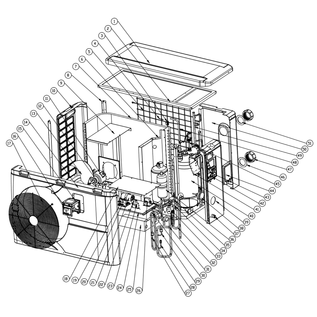
Hydro-Pro-warmtepomp (type 13) – opengewerkte tekening en reserveonderdelen
 Gecertificeerd webwinkel
 Eenvoudig retourneren binnen 14 dagen


Lijst met reserveonderdelen
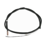
Hydro-Pro warmtepomp-omgevingstemperatuursensor T5 - 7010537
10,45 €

Temperatuursensor T1 voor de watertoevoer van de Hydro-Pro-warmtepomp - 7010534
10,45 €
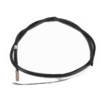
Flotide/MEGA - Temperatuursensor voor wateruitlaat T2 - 7010535
10,45 €

Ventilatormotor YDK-40-6 40 W voor Eco 12-warmtepomp - 7010522
151,45 €

Hydro-Pro - Ventilatorblad voor warmtepomp 490 mm × 125 mm, asgat 12 mm, rechtsdraaiend - 7010540
36,95 €

Hydro-Pro - LED-bedieningspaneel voor het in- en uitschakelen van warmtepompen XK 001 V1 MM011 - 7010515
168,45 €

Hydro-Pro - WiFi-bedieningspaneel met LED-verlichting voor het in- en uitschakelen van warmtepompen (type WiFi12iMM011) - 7023601
302,95 €
Hydro-Pro - Vervangende printplaat ZK 102 V1 voor warmtepomp type 13 - 7010514
168,45 €

Motorstartcondensator 60 µF, rond, AMP - 7010433
39,95 €

Condensator voor ventilatormotor van warmtepomp, 3 µF, vierkant insteektype - 7010417
23,95 €

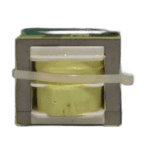
Flotide/MEGA - Warmtepomptransformator ZHL-03/EL-48 - 7010532
26,45 €

Schakelrelais CJX9B-25S/D 220–240 V AC voor Eco 12-warmtepomp - 7010519
142,95 €

Flotide/MEGA - Hogedrukschakelaar voor warmtepompen 3,6–4,2 MPa - 7024793
21,95 €

Flotide/MEGA - Lagedrukschakelaar 0,1–0,3 MPa (warmtepomp A3/32) - 7024791
21,95 €

Flotide/MEGA - PP-buisplug ½" buitendraad 10 bar zwart - 0121241
3,45 €

Manometer 0–55 bar R410A - 7010518
47,45 €

Hydro-Pro - Titanium warmtewisselaar voor ABS-warmtepomp type 13 - 7020786
525,95 €

Motor-aansluitblok 380–400 V / 16 A - 7010526
6,45 €

Flotide/MEGA - Waterstroomschakelaar voor warmtepompen met 32 mm lijmadapter - 7006471
51,45 €
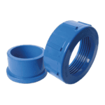
Hydro-Pro - Wateraansluitset 50 mm, lijmmof (set van 2) - 7014127
41,95 €

Beschrijving
Hydro-Pro-warmtepomp (type 13) – opengewerkte tekening en reserveonderdelen
This page provides the full exploded-view diagram and bill of materials for the Hydro-Pro Heat Pump Type 13, listed under factory reference 7018525. The diagram covers every major assembly of this swimming pool heat pump — from the refrigerant circuit and electrical enclosure through to the water-side connections and casing panels. Whether you are a pool owner carrying out routine maintenance or a technician diagnosing a fault, the numbered diagram and parts list below will help you pinpoint the exact component you need within minutes. Use the SKU shown against each position to order directly from our catalogue.
Hoe u het genummerde schema kunt gebruiken om uw onderdeel te vinden
Every numbered call-out on the diagram corresponds directly to a numbered row in the parts list below, so the two should always be read together. Begin by locating the general area of the unit where your part sits — for example, the electrical enclosure, the refrigerant circuit, or the water connections — then find the matching position number on the diagram. Once you have the position number, look up that row in the list to confirm the description and copy the SKU into the search bar or add it directly to your basket. Be aware that several position numbers carry letter suffixes: positions 3a, 3b, 3c, en 3d are four distinct temperature sensors, and positions 16a en 16b are two different LED display variants — ordering the wrong letter will result in an incompatible part. Where a position number appears more than once in the diagram (for instance on symmetrical brackets or repeated fastener points), the single BOM row covers all instances of that part. Parts marked without a SKU are structural or refrigerant-circuit components that are not offered as individual service parts; if a SKU is shown, that part is held in stock and available to order.
Main replaceable assemblies on the Hydro-Pro Heat Pump (Type 13)
The airside section handles the heat-exchange process between ambient air and the refrigerant. At its heart is the evaporator, supported by the motor bracket (pos. 9) and back grill (pos. 5), while the fan motor YDK-40-6 40W at position 11 (SKU 7010522) drives the 490 mm fan blade at position 13 (SKU 7010540) to draw air across the coil. The refrigerant circuit runs from the compressor (pos. 36) through the 4-way valve (pos. 33), electronic expansion valve (pos. 28), and into the titanium heat exchanger at position 40 (SKU 7020786), which transfers heat to the pool water; titanium construction makes this exchanger resistant to the chlorinated and saline water conditions typical in pool installations. Circuit protection is provided by the high-pressure switch at position 27 (SKU 7024793, rated 3.6–4.2 MPa) and the low-pressure switch at position 29 (SKU 7024791, rated 0.1–0.3 MPa), both of which are independently serviceable. The electrical enclosure contains the PC Board ZK 101 V1 at position 19 (SKU 7010514), the transformer ZHL-03/EL-48 at position 23 (SKU 7010532), the relay at position 26 (SKU 7010519), and two capacitors — a 60 µF unit at position 21 (SKU 7010433) and a 3 µF square plug-type at position 22 (SKU 7010417). On the water side, the flow switch with glue adapter at position 45 (SKU 7006471) confirms adequate water movement before allowing the unit to heat, while the water connection set at position 47 (SKU 7014127) provides the 50 mm glued-socket interface to the pool pipework. Four temperature sensors at positions 3a–3d monitor ambient air (T5, SKU 7010537), water inlet (T1, SKU 7010534), water outlet (T2, SKU 7010535), and pipe temperature (T3, SKU 7010533), giving the control board the data it needs to manage the refrigerant cycle efficiently.
Kiezen tussen varianten en verpakkingsgroottes
The most important variant choice on this unit is the LED display at position 16. Position 16a (SKU 7010515) is the standard On/Off display panel, reference XK 001 V1 MM011, while position 16b (SKU 7023601) is the Wi-Fi enabled version, reference WiFi02i MM101; these two panels use different control boards and communication protocols, so confirm which version is fitted before ordering by checking the label on the existing display or the wiring-box documentation. The four temperature sensors at positions 3a–3d are similarly distinct despite looking alike: each is calibrated and wired for a specific measurement point, so always match the position letter, not just the connector type. The pressure gauge at position 38 (SKU 7010518) and the PP plug at position 37 (SKU 0121241, ½” male thread, 10 bar rated) are single-item service parts — confirm thread size and pressure rating against the existing fitting before ordering a replacement. Where the BOM notes dimensions — such as the fan blade specification of 490 mm × 125 mm with a 12 mm clockwise-rotation hub — those figures must match your existing part exactly, as blades from other models in the Hydro-Pro range may share a similar appearance but differ in pitch or rotation direction.
