


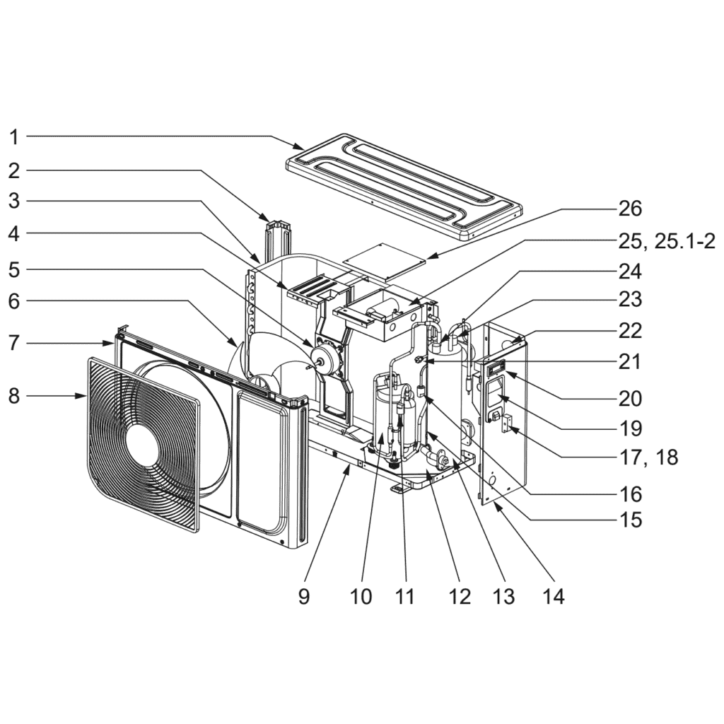
Pompa ciepła Flotide/MEGA, typ A, tryb włącz/wyłącz (typ A5/32) – widok rozłożony i części zamienne
 Certyfikowany sklep internetowy
 Łatwe zwroty w ciągu 14 dni


Lista części zamiennych
Flotide/MEGA - Heat Pump Fan Motor YKT-32-6-203L - 7024886
118,45 €

Flotide/MEGA - Heat Pump Fan Blade 427mm × 139mm Blue - 7024888
31,95 €

Flotide/MEGA – Przełącznik wysokiego ciśnienia do pomp ciepła 3,6–4,2 MPa – 7024793
21,95 €

Flotide/MEGA – przełącznik niskiego ciśnienia 0,1–0,3 MPa (pompa ciepła A3/32) – 7024791
21,95 €

Flotide/MEGA - LED Display & Controller Board RC-112E (WJL) for Plug & Play A3/32 Heat Pump - 7024894
67,45 €

Flotide/MEGA – Manometr do czynników chłodniczych 63 mm, zakres 0–65 bar, R32, przyłącze tylne 1/4" – 7025310
46,45 €

Flotide/MEGA – Przełącznik przepływu wody do pompy ciepła z adapterem do klejenia 32 mm – 7006471
51,45 €

Opis
Flotide/MEGA / MEGA Heat Pump Type A On/Off (Type A5/32) exploded view & spare parts
This page provides the full exploded-view diagram and bill of materials for the Flotide/MEGA / MEGA swimming pool heat pump sold under the On/Off control designation, model Type A5/32, factory reference 7024510. The Type A range is designed primarily for above-ground pools and uses R32 refrigerant together with a titanium heat exchanger, making it resistant to chlorinated and salt-treated water. The diagram covers all 26 numbered positions found on this unit, from the outer enclosure panels right through to the refrigeration circuit and electrical controls. Work through the numbered call-outs and the parts list below and you should be able to identify the component you need in just a few minutes.
Jak skorzystać z numerowanego schematu, aby znaleźć potrzebną część
Every numbered call-out printed on the exploded-view diagram corresponds directly to a row in the parts table below it, so start by locating the area of the unit where the fault or wear has occurred — for example the fan assembly, the refrigeration circuit, or the electrical enclosure. Once you have narrowed down the area, find the position number that points to your component in the diagram. Match that number to the same position number in the table to confirm the description and, where one is listed, the SKU you need to order. Bear in mind that some positions share a number across more than one location on the diagram: positions 17 and 18, for instance, both describe wire clips fitted in different spots on the chassis, so check both locations before concluding which one applies to your unit. Position 25 carries sub-positions — 25.1 and 25.2 — each representing a different capacitor value (25 µF and 35 µF respectively) housed within the same E-box assembly; you will need to read the rating marked on the failed capacitor before selecting the correct sub-item. Where a position has no SKU listed, the part is either supplied as part of a larger assembly or is not currently available individually — contact us if you are unsure. Always cross-reference the description column against what you can see on the unit, because component descriptions include key identifiers such as motor model codes, pressure ratings, and physical dimensions that confirm you have the right part.
Main replaceable assemblies on the Flotide/MEGA / MEGA Type A On/Off (A5/32)
The outer enclosure of the Type A5/32 consists of a top cover (pos. 1), a front panel (pos. 7), a right panel (pos. 14), a column (pos. 2), and the base chassis (pos. 9), all of which are structural rather than serviceable wear items. The fan section is the most commonly serviced assembly: the fan motor at position 5 (model YKT-32-6-203L, SKU 7024886) and the fan blade at position 6 (427 mm × 139 mm, SKU 7024888) can each be replaced independently, and the motor is held in place by the motor bracket at position 4. The refrigeration circuit includes the evaporator (pos. 3), the compressor at position 10 (factory code KSM93V11UDZ), and the titanium heat exchanger at position 13 — these components transfer energy from the outside air into the pool water and are central to the unit’s operation. Refrigerant circuit safety is managed by two pressure switches: the high-pressure switch at position 11 (rated 3.6–4.2 MPa, SKU 7024793) and the low-pressure switch at position 16 (rated 0.1–0.3 MPa, SKU 7024791); either switch can trigger a fault condition if the refrigerant circuit pressure moves outside its operating range. A pressure gauge at position 22 (0–65 bar, R32, SKU 7025310) and a needle valve at position 21 allow a qualified refrigeration engineer to monitor and adjust the circuit. On the water side, the water flow switch at position 23 (SKU 7006471) ensures the unit will only run when adequate water flow is present, while the water-in temperature sensor (pos. 15) and the water-out temperature sensor (pos. 24) provide the control board with the data it needs to regulate heating. The user interface is the LED display and PCB assembly at position 20 (model RC-112E (WJL), SKU 7024894). All electrical components for the main control board are grouped under the E-box assembly at position 25 (SKU 7024892), which is covered by the E-box cover at position 26.
Wybór między wariantami a rozmiarami opakowań
The most important variant distinction on this diagram sits within position 25, the E-box PCB assembly. Two capacitors are listed as sub-positions: 25.1 is a 25 µF round wired condensator (SKU 7010427) and 25.2 is a 35 µF round AMP-connector condensator (SKU 7010430). These two components are not interchangeable — the capacitance value and connector type must match the original exactly, so always check the labelling on the failed capacitor before ordering. Position 26, the E-box cover, also references a separate temperature sensor (SKU 7011007) and a repair kit (SKU 7027177) that bundles a temperature switch, thermal conductive paste, and wire connectors; if you are carrying out a more involved repair of the control enclosure, ordering the repair kit rather than individual components can save time and ensure you have the consumables you need. For any part where physical dimensions are given in the description — such as the 427 mm × 139 mm fan blade at position 6 — treat those measurements as mandatory selection criteria, because fitting a blade of a different diameter or pitch will affect airflow across the evaporator and reduce heating performance.
