



Ellenáramú rendszer, Stp Ss típus – szerelvényrrajz és pótalkatrészek
 Tanúsított online áruház
 Egyszerű visszaküldés 14 nap


Pótalkatrész-lista

Légszabályozó egység ellenáramú rendszerhez STP-SS – 7034191
2,95 €

O-gyűrű az STP-SS ellenáramú rendszerhez, 27 × 2,2 mm – 7034192
1,95 €

O-gyűrű az STP-SS ellenáramú rendszerhez, 17 × 1,5 mm – 7034193
1,95 €

Rozsdamentes acél panel ellenáramú rendszerhez STP-SS – 7034194
275,45 €

Cserecsavar az STP-SS ellenáramú rendszerhez, M6 × 40 mm – 7034195
0,95 €
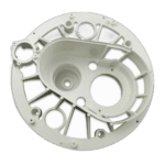
Fúvóka-ház az STP-SS ellenáramú rendszerhez – 7034196
31,45 €

Légszabályozó alap az STP-SS ellenáramú rendszerhez – 7034197
0,95 €

O-gyűrű az STP-SS ST2 ellenáramú rendszerhez, 16 mm – 7034199
1,95 €

M16 × 1,5-es kábelátvezető az STP-SS ellenáramú rendszerhez – 7034200
1,95 €

Pneumatikus tömlő az STP-SS ellenáramú rendszerhez, 3 × 8 mm – 7034201
24,95 €

Cseréfúvóka az STP-SS ellenáramú rendszerhez – 7034202
210,95 €

Légelszívó egység az STP ellenáramú rendszerhez – 7026755
11,95 €

4 mm külső átmérőjű pneumatikus tömlő, 7 m – STP ellenáramú rendszer – 7026756
49,95 €

Tartóperem az STP-SS ellenáramú rendszerhez, fehér – 7034208
11,45 €
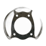
Rozsdamentes acél fogantyú ellenáramú rendszerhez STP-SS – 7034209
557,45 €

Housing Seal for Counter Current System STP-SS 230 × 272 × 2 mm - 7034210
22,95 €

Main Housing for Counter Current System STP-SS - 7034211
344,45 €

Fúvókaalap az STP-SS ellenáramú rendszerhez – 7034212
11,45 €

Védőcső STP-SS ellenáramú rendszerhez – 7034214
64,95 €

Cserecsavar M8 × 25 mm az STP-SS ellenáramú rendszerhez – 7034155
0,95 €

M6 Nut for Counter Current System Type STP-SS - 7034156
4,95 €

Ellenáramú mosóberendezés, 6 mm (STP-SS) – 7034157
2,95 €

Pump Flange for Counter-Current System STP / STP-SS - 7034158
267,95 €

Pump Body O-Ring No. 6 for Counter Current System STP-SS - 7017372
19,45 €
Ellenáramú rendszer tartóblokk 45 × 13 × 25,5 mm (STP-SS típus) – 7034159
4,95 €

Ellenáramú rendszer lábtámasz a BTP 2200 / 3000 / 4000 modellekhez – 7034160
45,95 €

Leeresztőcsavar O-gyűrűje az STP-SS ellenáramú rendszerhez – 7017373
3,95 €

Leeresztőcsap az STP típusú ellenáramú rendszerhez – 7017374
1,45 €
M6 × 120 mm-es csavar az STP típusú ellenáramú rendszerhez – 7034161
3,95 €

6,6 × 18 × 1,6 mm-es alátét az STP típusú ellenáramú rendszerhez – 7034162
2,95 €

75 × 5,3 mm-es O-gyűrű az STP típusú ellenáramú rendszerhez – 7034163
4,95 €

Ellenáramú rendszer STP bemeneti/kimeneti cső 75 mm – 7034164
21,95 €

Bemeneti/kimeneti anya az STP ellenáramú rendszerhez 2200 / 3000 / 4000 – 7034165
24,95 €

Szivattyútest az STP típusú ellenáramú rendszerhez – 7017375
285,95 €

Járókerék-anyca az STP típusú ellenáramú rendszerhez – 7017376
1,45 €

Járókerék az STP-2200 és STP-2200SS ellenáramú rendszerhez (21. alkatrész) – 7017377
53,95 €

Járókerék az STP-2200-T és STP-2200SS ellenáramú rendszerhez (400 V AC) – 7017378
53,95 €

Csere-járókerék az STP-3000-T és STP3000SS-T ellenáramú rendszerekhez (21. alkatrész) – 7017379
53,95 €

Járókerék az STP-4000 ellenáramú rendszerhez, 400 VAC – 7017380
53,95 €

22. számú mechanikus tömítés az STP típusú ellenáramú rendszerhez – 7017381
77,45 €

Leírás
Counter Current System, Type STP SS — exploded view & spare parts
This page covers the full exploded-view diagram and bill of materials for the Bosta Counter Current System, Type STP SS — a stainless steel pool jet system available in several motor variants including the STP-2200SS, STP-2200SS-T, STP-3000SS-T and STP-4000SS-T. The system pairs a single-stage centrifugal pump with a counterflow jet suitable for installation in concrete, liner, prefabricated and panelled swimming pools. The nozzle — 40 mm in diameter — allows regulation of both jet strength and air suction, and is directionally adjustable. Using the diagram and parts list together, you should be able to identify any numbered component and locate the correct SKU within a few minutes.
Hogyan lehet a számozott ábra segítségével megtalálni az alkatrészt?
Every numbered call-out printed on the exploded-view diagram corresponds directly to a numbered row in the parts list below the diagram. The most reliable way to work through it is to start with the area of the unit where the fault or wear is visible — for example, the nozzle head, the pump body, or the air regulation assembly — then cross-reference the position numbers shown in that region. Once you have the position number, find the matching row in the parts list to confirm the description and copy the SKU into the search bar or basket. Bear in mind that some position numbers appear more than once on the drawing: position 14 (Screw), position 17 (Tapping screw), position 22 (Tapping screw), and position 26 and 36 (Screw) are all generic fasteners used at multiple points across the assembly, so check that the circled number on the diagram is pointing to the correct fastener location before ordering. Position 55 is a particularly important example of a single number covering multiple variants — four different impeller SKUs share that position, each matched to a specific motor size — so read the variant description carefully before adding to your order. Where a position has no SKU listed (position 35, Motor), that item is not available as a standalone spare part through this listing and must be sourced separately. Always confirm the position description matches what you are looking at on the unit, as abbreviations and typographical variations in the BOM (such as “Nozzele bas” for nozzle base, or “Sucion valve” for suction valve) can occasionally cause confusion.
Main replaceable assemblies on the STP SS
The STP SS breaks down into three broad service areas, each containing several individually replaceable parts. The nozzle head assembly at the front of the unit is the most frequently serviced area: it comprises the nozzle (pos. 21), nozzle housing (pos. 15), nozzle base / air suction unit (pos. 23), and the air regulation knob (pos. 10) with its base (pos. 16). The nozzle, suction and pneumatic switch are positioned in the front cover panel of the equipment, which means this panel — the stainless steel face panel at pos. 13 — typically needs to come away first before internal nozzle components can be accessed. Sealing across the nozzle head is handled by a family of O-rings at positions 11, 12, 18 and 24, and the housing seal at pos. 29; these are the first items to inspect when the unit develops a water or air leak. The pneumatic air circuit — which operates the pneumatic switch to start and stop the pump without mains voltage at the poolside — runs via the pneumatic hose (pos. 20), the air suction hose (pos. 32), the suction valve (pos. 31), and the cable gland M16 (pos. 19) that keeps the wiring entry watertight. The pump body assembly covers the wetted end of the centrifugal pump: the pump body itself (pos. 50) is sealed against the main housing by the O-ring pump body (pos. 40), while the drain plug (pos. 44) and its O-ring (pos. 43) allow the pump to be emptied for winter or servicing. Flow connections are made through the inlet pipe (pos. 48) with inlet nut (pos. 49) and the outlet pipe (pos. 52) with outlet nut (pos. 53), each sealed by their own O-rings (pos. 47 and 51). The rotating heart of the pump is the impeller (pos. 55) retained by the impeller nut (pos. 54); both are common wear items and should be checked whenever pump performance drops. The back plate (pos. 25) and support flange (pos. 27) form the structural bridge between the pump body and the wall fitting, while the foot support (pos. 42) and support block (pos. 41) carry the assembly’s weight and must be intact to prevent vibration damage.
A változatok és a csomagméretek közötti választás
The most critical variant choice on this diagram is the impeller at position 55, where four distinct SKUs cover four motor/power combinations: SKU 7017377 fits the STP-2200SS, SKU 7017378 the STP-2200SS-T, SKU 7017379 the STP-3000SS-T, and SKU 7017380 the STP-4000SS-T. Fitting the wrong impeller will result in poor flow performance or mechanical interference, so confirm your exact model designation — usually found on the motor or control box label — before ordering. The control boxes themselves are also model-specific: the BOM notes four separate control box references (SKUs 7034397 through 7034400) covering different amperage ranges (4–6.3 A, 6–10 A, and 9–14 A) matched to specific motor sizes, so the same care applies when replacing that electrical component. For fasteners such as the screws (pos. 14, 26, 36), tapping screws (pos. 17, 22), nut (pos. 37), washer (pos. 38, 46), and bolt (pos. 45), note that each has its own SKU reflecting specific thread type, diameter, or head style — ordering by position number and SKU together, rather than by generic description alone, is the safest way to ensure you receive the correct fastener for reassembly.
