Promatic Chlorinator (MPS16 / MPS24 / MPS36 / MPS50) exploded view & spare parts
 Certified online store
 Easy returns within 14 days


Spare parts list

Davey - ProMatic ESC 24 / ESC 24Ph Salt Chlorinator Transformer - M1715
267,45 €
Davey - ProMatic ESC Controller Replacement Transformer (ESC 36 / ESC 48 / ESC 40) - M1788
333,95 €
Davey - ProMatic MPS36 / MPS50 Control Unit Fuse 5A - M2906
3,95 €
Davey - ProMatic MPS / ESR / ESC Electronic Control Board (PCB) — ProMatic 16 - M111716EUSP
508,45 €
Davey - ProMatic 24 Electronic Control PCB (MPS / ESR / ESC) - M111724EUSP
508,45 €
Davey - ProMatic MPS / ESR / ESC 36 Salt Chlorinator Electronic Control Board (PCB) - M1117A36EUSP
508,45 €
Davey - ProMatic MPS 40 & MPS 50 Control PCB (Electronic Board) - M1117A48EUSP
508,45 €
Davey - ProMatic ESC / ESCpH Cell Cable Assembly - M2679
102,45 €
Davey – ProMatic ESR/ESC Salt Chlorinator Cell Head O-Ring - M1217
6,95 €
Davey - ProMatic ESC / MCS Salt Chlorinator Cell Head Assembly with Glands - M1224H5SP
75,45 €
Davey - ProMatic MPS50 Barrel Union Reducing Tail 80mm to 50mm - M1576
23,95 €
Davey - Gas Sensor Service Kit for ESC Max / Plus Chlorinator - 32746
17,95 €
Davey - ProMatic MPS / ESR / ESC Gas Detector O-Ring - M1203
2,95 €
Davey - ProMatic Salt Chlorinator Cell Housing (ESR / ESC / MPS) - M1249
97,95 €
Davey - ProMatic Salt Chlorinator Cell Pipe Adapter 63/50 - M1215
7,95 €

Description
Davey Promatic Chlorinator (MPS16 / MPS24 / MPS36 / MPS50) exploded view & spare parts
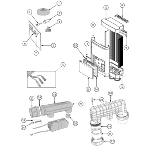
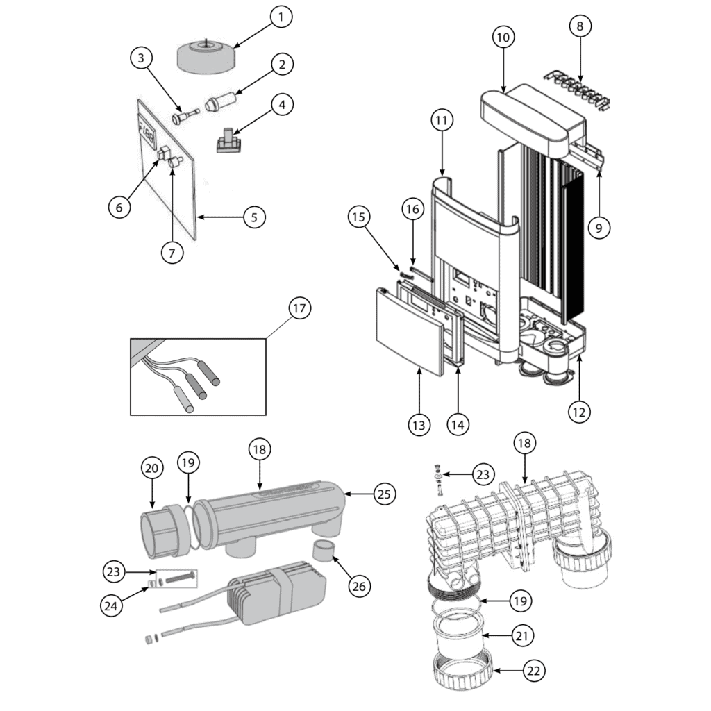
This page covers the complete exploded-view diagram and bill of materials for the Davey Promatic salt water chlorinator range, spanning four pool-size variants: MPS16, MPS24, MPS36, and MPS50, supplied to the European market under factory references MPS16CE, MPS24CE, MPS36CE, and MPS50CE. The Promatic is a residential salt water chlorinator designed for straightforward, reliable pool sanitation. The diagram on this page shows every replaceable component — from the electrolytic cell and control PCB through to the housing panels and door linkages — exactly as Davey assembled it from the factory. Use the numbered call-outs alongside the parts list below to identify precisely what you need, and you should have your SKU ready to order within minutes.
How to use the numbered diagram to find your part
Every numbered call-out printed on the diagram corresponds directly to a position number (pos.) in the parts table below the image — locating position 5, for example, will take you straight to the correct PCB row for your model. Start by identifying the general area of the unit where the fault or wear is visible — for instance, the electrical enclosure, the cell assembly, or the outer housing — then trace the relevant call-out number from the diagram to the matching row in the table. Because several positions share the same number across different model variants, always read the description column in full: position 1 covers two different transformers (SKUs M1715 and M1788), position 3 covers two different fuse ratings, and position 18 covers three different electrolytic cells, each tied to a specific model. Similarly, position 5 has four separate PCB SKUs — one for each model in the range — so confirming your model designation (MPS16CE, MPS24CE, MPS36CE, or MPS50CE) before adding to your basket is essential. Where a position offers an alternative size or configuration, such as the barrel union tails at position 21, both options are listed; take note of the pipe diameter your installation uses before ordering. If you are unsure which variant you have, check the rating label on the inside of the front cover of the control unit, where the full model reference is printed.
Main replaceable assemblies on the Promatic MPS Series
The Promatic is built around two main sections: the power and control enclosure and the cell assembly, and most service calls involve a component from one of these two areas. In the control enclosure, position 1 is the transformer — a core wear item available in two ratings: SKU M1715 for the MPS24, and the higher-output M1788 covering the MPS36 and MPS50. The fuse holder (position 2, SKU M2953) is shared across all models, but the fuse itself at position 3 is rated 3 A for the MPS16 and MPS24 (M2902) and 5 A for the MPS36 and MPS50 (M2906) — fitting the wrong rating is a common and easily avoided mistake. The filter board at position 4 and the main PCB at position 5 are both model-specific; the PCB in particular carries the chlorine output logic, so an incorrect SKU will result in the unit producing the wrong chlorine level for your pool volume. User-facing controls include the power switch (position 6, SKU M2004) and the chlorine control knob (position 7, SKU M1521), both of which are straightforward to replace without specialist tools. The cell assembly at positions 17–26 is where the salt electrolysis actually takes place: the cell cord assembly (position 17) connects the control unit to the electrolytic cell (position 18), which is the highest-wear component in the system and again model-specific across three SKUs. The gas detector at position 23 monitors for gas build-up inside the cell body and is available in two variants: SKU M1103 for the MPS16, MPS24, and MPS36, and SKU 32746 for the MPS50. Completing the wet side of the system, the cell body (position 25, SKU M1249), cell head assembly (position 20, SKU M1224H5SP), and cell adaptor (position 26, SKU M1215) handle water flow and sealing around the electrodes, with O-rings at positions 19 and 24 providing the primary fluid seals.
Choosing between variants and pack sizes
Several positions in this diagram carry more than one SKU, and selecting the wrong one will result in a part that either will not fit or will not perform correctly. The most important split runs along model capacity lines: the MPS16 and MPS24 share many electrical components (fuse rating, cell O-ring M1217, cell cord M2679, and cell head assembly M1224H5SP), while the MPS36 and MPS50 step up to heavier-duty equivalents. The MPS50 is the most distinct variant in the range — it uses its own cell (M4922REP), its own cell cord (M2679-10), a different O-ring (M1573), and a dedicated barrel union system at positions 21 and 22, where you must also choose between the standard 80 mm barrel union tail (M1572) and the reducing tail that steps down from 80 mm to 50 mm (M1576) to suit your pipework. The MPS50CE operates at 220–240 V / 50–60 Hz and uses a 5 A fuse, so ensure any electrical replacements reflect those ratings. Always cross-reference your full factory reference (e.g. MPS36CE) against both the position number and the description column before finalising your order.