



Hydro-Pro Heat Pump (Type 7) exploded view & spare parts
 Certificato negozio online
 Resi facili entro 14 giorni


Elenco dei ricambi
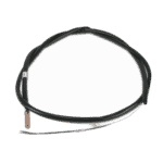
Hydro-Pro Heat Pump Ambient Temperature Sensor T5 - 7010537
10,45 €

Water Inlet Temperature Sensor T1 for Hydro-Pro Heat Pump - 7010534
10,45 €
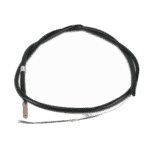
Flotide/MEGA - Water Outlet Temperature Sensor T2 - 7010535
10,45 €

Pool Heat Pump Fan Motor YDK-25-6 25W - 7010521
92,45 €

Pool Heat Pump Fan Blade 400mm × 118mm, 8mm Bore, Counterclockwise - 7010538
31,45 €

Hydro-Pro - Heat Pump LED On/Off Control Display Panel XK 001 V1 MM011 - 7010515
168,45 €

Hydro-Pro - Heat Pump WiFi LED On/Off Control Panel (Type WiFi12iMM011) - 7023601
302,95 €

Flotide/MEGA - Heat Pump Transformer ZHL-03/EL-48 - 7010532
26,45 €

Flotide/MEGA - Motor Run Capacitor 25µF for SC100 / SC150 Pool Pump - 7010427
57,45 €

Motor Run Capacitor 2 µF Square Plug-in Type - 7010416
3,45 €

Hydro-Pro - Heat Pump Control PC Board ZK 101 V1 - 7010513
168,45 €

Flotide/MEGA - Heat Pump High Pressure Switch 3.6–4.2 MPa - 7024793
21,95 €

Flotide/MEGA - Low Pressure Switch 0.1–0.3 MPa (Heat Pump A3/32) - 7024791
21,95 €

Hydro-Pro - Titanium Heat Exchanger for Type 7 ABS Heat Pump - 7020784
473,45 €

Flotide/MEGA - PP Pipe Plug ½" Male Thread 10 Bar Black - 0121241
3,45 €

Pressure Gauge 0–55 Bar R410A - 7010518
47,45 €
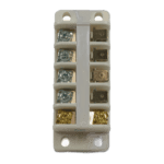
Hydro-Pro - Heat Pump Terminal Block 220–240 V / 32 A (16 mm²) - 7010527
20,95 €

Flotide/MEGA - Heat Pump Water Flow Switch with 32 mm Glue Adapter - 7006471
51,45 €
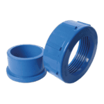
Hydro-Pro - Water Connection Set 50mm Glue Socket (Pack of 2) - 7014127
41,95 €

Descrizione
Hydro-Pro Heat Pump (Type 7) exploded view & spare parts
This page provides the full exploded-view diagram and numbered bill of materials (BOM) for the Hydro-Pro Heat Pump (Type 7), factory reference 7018523. The Type 7 is the entry-level model in the Hydro-Pro fixed-speed range — a compact, air-source pool heat pump built around a titanium heat exchanger, a low-noise rotary compressor, and a straightforward LED control panel. Every position shown in the diagram corresponds to a row in the parts list below, giving you a direct path from a faulty component to the correct replacement SKU. Most visitors find the part they need within a few minutes using the method described below.
Come utilizzare lo schema numerato per individuare il proprio componente
Start by locating the area of the unit where you are experiencing the fault — for example, the airside (fan and evaporator), the waterside (heat exchanger and plumbing connections), or the electrical enclosure. Once you have identified the general area, find the call-out number in the diagram that points to the specific component. Each number maps directly to a row in the parts list, where you will find a description and, where available, a stockable SKU ready to add to your basket. Bear in mind that some position numbers carry letter suffixes — positions 3a, 3b, 3c, and 3d are four distinct temperature sensors, and positions 15 and 15b are two different LED display variants — so always read both the number and the suffix before ordering. Check the written description carefully against what you can see on your unit, particularly for electrical components such as capacitors (positions 20 and 22), which differ in capacitance, physical format, and connection type. If a position number appears more than once in the diagram at different locations — which can happen with fasteners, clips, or rubber seals — the description column will clarify which instance applies. Where no SKU is listed against a position, the component is either a structural panel or a refrigerant-circuit item that requires trade fitting; contact our team for guidance on those parts.
Main replaceable assemblies on the Hydro-Pro Heat Pump (Type 7)
The Type 7 is broadly divided into four service areas. The airside assembly sits at the top of the unit and comprises the evaporator (pos. 7), the fan motor YDK-25-6 at position 11, and the 400 mm fan blade at position 12 — these are the most frequently replaced wear items after several seasons of outdoor use. The electrical enclosure houses the main PC board ZK 101 V1 (pos. 23), the transformer ZHL-03/EL-48 (pos. 19), and two capacitors: a 25 µF round wired type (pos. 20) and a 2 µF square plugged type (pos. 22); all four carry individual SKUs and are stocked separately because each serves a different circuit function. The control and display section at the front panel (pos. 13) includes the LED display at position 15 or 15b depending on which control board variant your unit was built with. The refrigerant and waterside circuit contains the titanium heat exchanger at position 37 (SKU 7020784), protected by a high-pressure switch rated 3.6–4.2 MPa (pos. 26, SKU 7024793) and a low-pressure switch rated 0.1–0.3 MPa (pos. 30, SKU 7024791). The water flow switch at position 44 (SKU 7006471) is a safety-critical component that prevents the unit from operating without adequate water flow, and is a common first check when the pump trips without an obvious cause. Pool water enters and leaves through the water connection set at position 49 (SKU 7014127), which uses a 50 mm glue socket. Finally, the pressure gauge at position 39 (SKU 7010518) allows refrigerant-circuit pressures to be read without opening the system. The terminal block at position 42 (SKU 7010527) is rated 220–240 V / 32 A and is the correct mains connection point for this model.
Choosing between variants and pack sizes
The most important variant decision on this diagram is the LED display. Position 15 refers to the standard LED display On/Off unit carrying model code XK 001 V1 MM011 (SKU 7010515), while position 15b is the Wi-Fi-enabled display, model code WiFi02iMM101 (SKU 7023601). Fitting the wrong display will result in a control-board communication mismatch, so check the code printed on your existing board before ordering. The temperature sensors at positions 3a through 3d also carry distinct SKUs (7010537, 7010534, 7010535 respectively for T5, T1, and T2), even though they may look similar externally — the probe length, connector type, or calibration range can differ between positions, so do not substitute one for another. For the capacitors, the values 25 µF and 2 µF are not interchangeable, and the physical format (round wired versus square plugged) must also match the mounting clip and wiring harness already in the unit. The ½-inch male-thread plug at position 38 (SKU 0121241) is a standard PP fitting rated to 10 bar; if you are replacing a damaged plug, confirm the thread standard on your pipework before fitting.
