


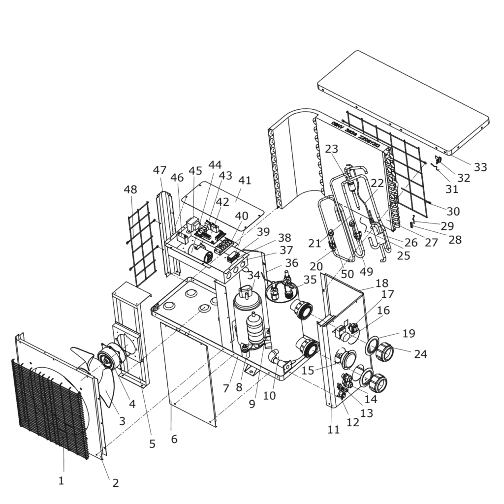
Nr. Description For exploded view & spare parts
 Certified online store
 Easy returns within 14 days


Spare parts list

Motor Fan Blade 320mm × 135mm, 7mm Bore, Counterclockwise - 7010542
15,95 €

Pool Heat Pump Fan Motor YDK-18-6 18W - 7010520
83,95 €

Water Inlet Temperature Sensor T1 for Hydro-Pro Heat Pump - 7010534
10,45 €

Pressure Gauge 0–55 Bar R410A - 7010518
47,45 €

Adjustable Thermostat - 7010517
83,95 €

Mechanical Switch Black/Red - 7010516
41,95 €
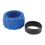
Water Connection 50mm Compression Socket - 7014126
41,95 €
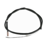
Hydro-Pro Heat Pump Ambient Temperature Sensor T5 - 7010537
10,45 €
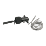
Water Flow Switch for ECO Hydro-Pro Heat Pump - 7010531
120,95 €

Motor Terminal Block 380–400 V / 16 A - 7010526
6,45 €

Control Circuit Board ZL 6671 - 7010512
168,45 €
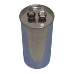
Flotide/MEGA - Pool Pump SB Run Capacitor 35 µF Round - 7010430
34,95 €

Motor Run Capacitor 2 µF Square Plug-in Type - 7010416
3,45 €
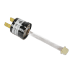
Low Pressure Protection Switch 0.3–0.6 MPa Black - 7010529
21,95 €
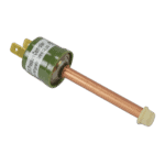
High Pressure Protection Switch 2.9/2.3 MPa (Green) - 7010530
21,95 €

Heat Pump Winter Cover 75 × 26 × 47 cm - 7009812
60,95 €

Description
Bosta ECO 3 & ECO 5 heat pump exploded view & spare parts
This page covers the complete exploded-view diagram and bill of materials for the Bosta ECO 3 and ECO 5 swimming pool heat pumps, referenced internally as document 7008312/13. Both models share the same overall cabinet architecture and refrigeration circuit layout, so a single diagram serves them both; where a component differs between the two outputs, the BOM makes that distinction clear. Whether you are a pool owner carrying out routine maintenance or a technician diagnosing a fault in the field, the numbered diagram and the parts list below will let you pinpoint the exact component you need in a matter of minutes.
How to use the numbered diagram to find your part
Every numbered call-out printed on the diagram corresponds directly to a row in the parts list table on this page — find the area of the unit that concerns you, note the position number shown on the diagram, then look up that number in the BOM to confirm the description and retrieve the SKU for ordering. Work methodically: start with the general zone (air-side at the front, refrigeration circuit in the centre, electrical box on the side), narrow down to the sub-assembly, and then match the call-out number. Bear in mind that some position numbers carry lettered suffixes — for example, positions 8a/8b, 10a/10b, 20a/20b, 21a/21b, 22a/22b, 23a/23b, 26a/26b, and 27a/27b — where the “a” variant belongs to the ECO 3 and the “b” variant belongs to the ECO 5; ordering the wrong letter means ordering a part sized for the wrong model. A small number of positions in this diagram share the same numeral across visually separate locations on the drawing (for instance, certain fastener and clip positions); always read the full description in the BOM row, not just the number, before adding a SKU to your basket. If a row shows no SKU, that part is either sourced as part of a larger assembly or is not currently held as an individual line item — contact us before ordering a substitute. Checking the description against the physical part in front of you — dimensions, connector type, pressure rating — is always the safest final confirmation before placing an order.
Main replaceable assemblies on the Bosta ECO 3 & ECO 5
The air circuit at the front of the unit is built around the front grill (pos. 1), front panel (pos. 2), and the 320 mm × 135 mm fan blade (pos. 3) driven by an 18-watt fan motor (pos. 4) held in place by the fan motor bracket (pos. 5); the back grill (pos. 30) and side grills (pos. 48) complete the airflow enclosure, and the top cover (pos. 33) seals the cabinet. The refrigeration circuit is the heart of both models: each variant has its own compressor — the ECO 3 compressor at pos. 8a and the ECO 5 compressor at pos. 8b — paired with a dedicated titanium heat exchanger (pos. 10a for the ECO 3, pos. 10b for the ECO 5) and a corresponding model-specific evaporator (pos. 27a / 27b). Refrigerant is managed through the suction valve (pos. 13), capillary (pos. 25), and a network of model-specific piping covering the suction pipes (pos. 20a/20b), exhaust pipes (pos. 21a/21b), and the connecting pipes between the four-way valve and the evaporator and heat exchanger (pos. 22a/22b and 23a/23b). Safety is handled by the low-pressure protection switch (pos. 49, SKU 7010529) and the high-pressure protection switch (pos. 50, SKU 7010530), along with the pressure gauge rated at 5.5 mPA/100 °C (pos. 15, SKU 7010518). The water circuit includes the titanium heat exchanger noted above, the water flow switch (pos. 35, SKU 7010531), the water-inlet temperature sensor (pos. 9, SKU 7010534), the water inlet/outlet bolt (pos. 19), the water connection nut (pos. 24, SKU 7014126), and the drainage hole plug (pos. 12). The electrical box assembly (pos. 37) contains the PC board ZL 6671 (pos. 42, SKU 7010512), terminal blocks (pos. 40, SKU 7010526), the thermostat (pos. 16, SKU 7010517), the mechanical switch (pos. 17, SKU 7010516), and the maintain board (pos. 6), all protected by the controller box cover (pos. 41) and secured with cable fixing clamps (pos. 38 and 39). Sensors rounding out the system include the ambient temperature sensor (pos. 31, SKU 7010537) retained by its clip (pos. 32), and the pipes temperature sensor collet (pos. 28).
Choosing between variants and pack sizes
The most important variant decision on this diagram is the ECO 3 versus ECO 5 split, which affects eight distinct position groups: compressors (8a/8b), titanium heat exchangers (10a/10b), suction pipes (20a/20b), exhaust pipes (21a/21b), four-way valve to evaporator pipes (22a/22b), four-way valve to heat exchanger pipes (23a/23b), collection pipes (26a/26b), and evaporators (27a/27b). Always confirm which model is installed before selecting a lettered variant, as refrigerant pipe dimensions and connection fittings differ between the two output classes and an incorrect part will not seat or seal correctly. For electrical components such as the capacitors — the 35 µF unit at pos. 44 (SKU 7010430) and the 2 µF unit at pos. 46 (SKU 7010416) — the capacitance value and voltage rating must match exactly, so double-check both figures against your existing component before ordering. Where a position carries no lettered suffix, such as the fan blade (pos. 3, specified at 320 mm × 135 mm) or the pressure gauge (pos. 15, rated at 5.5 mPA/100 °C), the stated dimension or rating is the only variant available for this product family and applies equally to both the ECO 3 and the ECO 5.
