



Hydro-Pro Heat Pump, Type Z Inverter (Type Z16/32) exploded view & spare parts
 Certified online store
 Easy returns within 14 days


Spare parts list

Flotide/MEGA - Ambient Temperature Sensor TH1 with Plug Connector (6×4) - 7020259
15,95 €

Hydro-Pro - Evaporator Heating Belt 230V 65W 2000mm - 7020274
58,95 €

Hydro-Pro - Heat Pump Fan Motor ZWB378D02B 120W - 7021812
414,45 €

Hydro-Pro - Inverter Heat Pump Fan Blade 496mm × 150mm, 12mm Bore, Anticlockwise - 7021815
80,95 €

Flotide/MEGA - Inverter Heat Pump LED Display SHHCLEDV2MM101 - 7021826
226,95 €

Flotide/MEGA - Compressor Crankcase Heating Belt 230V 35W 390mm - 7020268
43,95 €

Flotide/MEGA - Refrigerant Pressure Gauge 63 mm 0–65 bar R32 Rear Connection 1/4" - 7025310
46,45 €
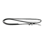
Flotide/MEGA - Pipe Temperature Sensor TH2 with 6×4 Plug - 7020260
12,45 €

Flotide/MEGA - Heat Pump High Pressure Switch 3.6–4.2 MPa - 7024793
21,95 €

Flotide/MEGA - Low Pressure Switch 0.1–0.3 MPa (Heat Pump A3/32) - 7024791
21,95 €

Flotide/MEGA - Exhaust Temperature Sensor TH3 with Plug (6×4) - 7020261
15,95 €
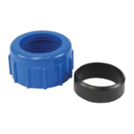
Water Connection 50mm Compression Socket - 7014126
41,95 €

Flotide/MEGA - Water Flow Switch with VH-2 Plug (9×7 mm) - 7020257
100,95 €

Flotide/MEGA - Water Outlet Temperature Sensor TH5 with Plug (6×4) - 7020262
15,95 €
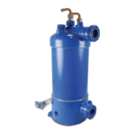
Hydro-Pro - Titanium Heat Exchanger for Type Z Inverter Heat Pump (Z16/32) - 7025164
445,95 €

Flotide/MEGA - Water Inlet Temperature Sensor TH6 with Plug (6×4) - 7020263
15,95 €

Flotide/MEGA - PP Pipe Plug ½" Male Thread 10 Bar Black - 0121241
3,45 €

Hydro-Pro - Main Control Board IB020R3A (HWM1W-5E00) for Type Z Inverter Heat Pump Z14/32 & Z16/32 - 7025157
686,45 €

Description
Hydro-Pro Heat Pump, Type Z Inverter (Type Z16/32) exploded view & spare parts
This page provides the full exploded-view diagram and bill of materials for the Hydro-Pro Heat Pump, Type Z Inverter, model Z16/32, covered by factory reference 7024518. The Z16/32 is rated at 16 kW output and is suitable for pools with up to 85 cubic metres of water. As an inverter heat pump, it varies its heating capacity to suit weather conditions, automatically adjusting compressor and fan speeds to balance noise level and energy consumption. The diagram covers all 68 numbered positions — from the outer cabinet panels through to the refrigerant circuit and water-side components — so you can identify the exact part you need in a matter of minutes.
How to use the numbered diagram to find your part
Every numbered call-out printed on the exploded-view diagram corresponds directly to a row in the parts list table on this page. Start by locating the area of the unit where your part lives — for example, the air-side (fan and evaporator section), the refrigerant circuit, or the water-side (heat exchanger and flow switch) — and then find the matching position number in that area of the diagram. Once you have the number, locate the same row in the parts list to read the full description and, where available, the SKU you need to add to your basket. Bear in mind that some generic components such as clips (positions 10 and 31) and rubber rings (positions 54 and 60) share identical descriptions but appear in different locations on the unit; always confirm the position number against the diagram rather than the description alone. Position 66 is listed as N/A and does not have an orderable part associated with it, so if your diagram shows 66, please contact us for guidance. Where a position carries a lettered suffix — most notably 20a and 20b — there are two distinct variants for that position, and choosing the wrong one will result in a part that does not fit your specific build of the unit. Finally, not every position currently has a stocked spare-part SKU; positions shown without a SKU are either non-serviceable assemblies or parts not yet listed individually — again, contact us if you are unsure.
Main replaceable assemblies on the Hydro-Pro Heat Pump Type Z Inverter (Z16/32)
The air-handling section sits at the top of the unit and draws ambient air across the evaporator. The fan assembly consists of the fan motor (position 12, SKU 7021812) mounted on its bracket (position 8), driving a 496 mm × 150 mm anticlockwise fan blade with a 12 mm centre hole (position 15, SKU 7021815) through the DC motor casing tube (position 14). The evaporator (position 6) is protected against frost damage by a dedicated evaporator heating belt rated at 230 V / 65 W with a 2,000 mm wrap length (position 11, SKU 7020274). The refrigerant circuit is anchored by the inverter compressor SVB172FNPMC (position 26), which is insulated from structure-borne noise by anti-vibration hammers (position 25) and kept warm during cold-weather standby by the compressor heating belt rated at 230 V / 35 W / 390 mm (position 24, SKU 7020268). Refrigerant flow is managed by the 4-way reversing valve (position 47) and the electronic expansion valve (position 49), with system pressures monitored by a high-pressure switch rated 3.6–4.2 MPa (position 42, SKU 7024793) and a low-pressure switch rated 0.1–0.3 MPa (position 43, SKU 7024791); a dedicated R32 pressure gauge (position 29, SKU 7025310) is also part of this circuit. The water-side circuit centres on the titanium heat exchanger specific to the Z16/32 (position 59, SKU 7025164), fed through a 50 mm compression-type water connection set (position 52, SKU 7014126); water flow is confirmed by the VH-2 flow switch (position 53, SKU 7020257). Four temperature sensors provide the controller with real-time data: the ambient sensor TH1 (position 2, SKU 7020259), the pipe sensor TH2 (position 39, SKU 7020260), the exhaust sensor TH3 (position 45, SKU 7020261), and the water outlet sensor TH5 (position 57, SKU 7020262) together with the water inlet sensor TH6 (position 61, SKU 7020263). The electrical section is built around the main inverter control board HWM1W-5E00 IB020R3A (position 64, SKU 7025157), housed in the electric box (position 65) behind the electric box cover (position 63), with the reactor (position 9) conditioning the power supply to the inverter drive.
Choosing between variants and pack sizes
The most important variant choice on this diagram is at position 20, which covers the user-interface display. Position 20a is the LED display module (SHHCLEDV2MM101, SKU 7021826), while position 20b is the colour TFT display (TSiV1, SKU 7025263). These are not interchangeable — the correct display depends on which version was fitted to your unit at the factory, and substituting one for the other will result in an incompatible connector or control interface. Check the label on your existing display board or cross-reference with your original purchase documentation before ordering. Where sealing components are involved — such as the O-ring (position 55), the red rubber ring (position 54), and the blue rubber ring (position 60) — fitting the correctly specified item is equally important, as even a small difference in cross-section diameter or material hardness can cause a water leak at the heat exchanger connections. If you are ordering consumable sensor plugs (positions 2, 39, 45, 57, and 61), note that all five use a 6×4 plug format and are individually listed by SKU, so confirm the position number in the diagram to ensure you order the sensor for the correct circuit point.
