


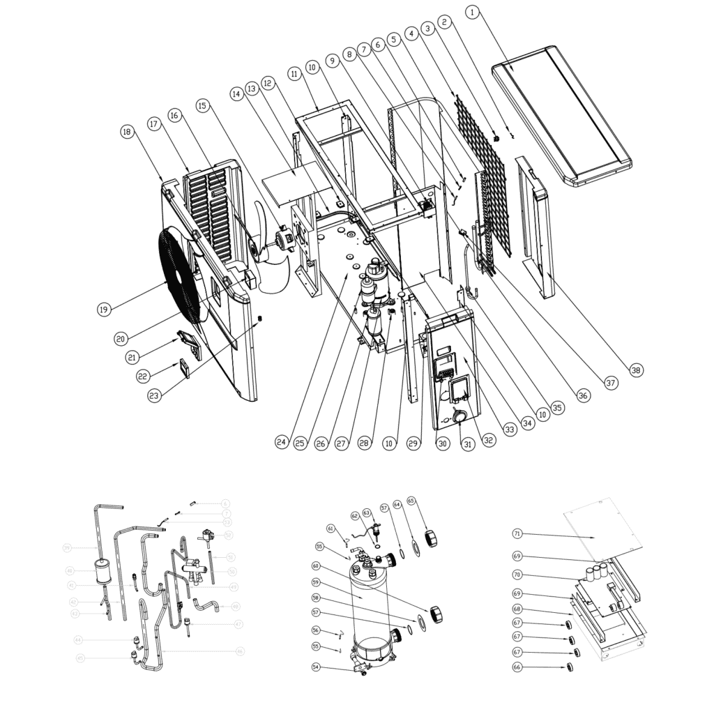
Hydro-Pro Heat Pump, Type Inverter (Type Xp21Dcsi+) exploded view & spare parts
 Certified online store
 Easy returns within 14 days


Spare parts list

Flotide/MEGA - Ambient Temperature Sensor TH1 with Plug Connector (6×4) - 7020259
15,95 €
Flotide/MEGA - Pipe Temperature Sensor TH2 with 6×4 Plug - 7020260
12,45 €

Hydro-Pro - Evaporator Heating Belt 230V 65W 1700mm - 7020273
56,95 €

Hydro-Pro - Heat Pump Fan Motor ZWB378D02B 120W - 7021812
414,45 €

Hydro-Pro - Replacement Fan Blade 554mm × 148mm, 10mm Bore, Anticlockwise - 7021816
99,45 €

Flotide/MEGA - Waterproof Display Box for Inverter Heat Pump (Type Xp05Csie) - 7010543
31,45 €

Hydro-Pro - Inverter Heat Pump LED Display Controller SHHCLEDMM101 - 7020256
226,95 €

Flotide/MEGA - LED Display Panel with Wi-Fi for Inverter Heat Pump (WiFi02iMM011) - 7023600
252,45 €

Flotide/MEGA - Compressor Crankcase Heating Belt 230V 35W 320mm - 7020269
45,45 €

Pressure Gauge 0–55 Bar R410A - 7010518
47,45 €

Flotide/MEGA - Low Pressure Switch 0.1–0.3 MPa (Heat Pump A3/32) - 7024791
21,95 €

Flotide/MEGA - Low Pressure Switch 0.2–0.35 MPa (Inverter Heat Pump Xp05Csie) - 7024792
21,95 €

Flotide/MEGA - Heat Pump High Pressure Switch 3.6–4.2 MPa - 7024793
21,95 €

Flotide/MEGA - Exhaust Temperature Sensor TH3 with Plug (6×4) - 7020261
15,95 €

Flotide/MEGA - PP Pipe Plug ½" Male Thread 10 Bar Black - 0121241
3,45 €

Flotide/MEGA - Water Inlet Temperature Sensor TH6 with Plug (6×4) - 7020263
15,95 €
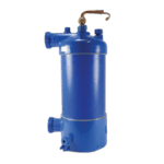
Hydro-Pro - Titanium Heat Exchanger for Inverter 21 Heat Pump - 7021822
1.261,95 €

Flotide/MEGA - Water Outlet Temperature Sensor TH5 with Plug (6×4) - 7020262
15,95 €

Flotide/MEGA - Water Flow Switch with VH-2 Plug (9×7 mm) - 7020257
100,95 €

Hydro-Pro - Main Control Board for Inverter 21 Heat Pump (Xp21Dcsi+) - 7020762
1.101,95 €

Description
Hydro-Pro Heat Pump, Type Inverter (Type Xp21Dcsi+) exploded view & spare parts
This page presents the full exploded-view diagram and bill of materials for the Hydro-Pro Heat Pump, Type Inverter (Type Xp21Dcsi+), identified by Hydro-Pro factory reference 7018549. The diagram covers every major assembly of this DC inverter pool heat pump — from the refrigerant circuit and titanium heat exchanger through to the control electronics and external casing panels. Whether you are a pool owner tracing an intermittent fault or a technician carrying out a scheduled service, the numbered diagram and parts list below allow you to pinpoint the exact component you need in minutes. Where a spare part carries a PoolPartHub SKU, it can be ordered directly from this page.
How to use the numbered diagram to find your part
Every call-out number printed on the exploded-view diagram corresponds directly to a numbered row in the parts table beneath it. Begin by identifying the general area of the unit where the suspect or failed component sits — for example, the refrigerant circuit at the rear, the fan assembly at the top, or the water-side connections on the hydraulic block. Once you have narrowed the area, locate the matching number on the diagram and cross-reference it to the parts table to confirm the description and, where available, the SKU. Pay close attention to call-outs that share the same number in more than one location: for instance, positions 60 and 65 both describe a Water connection set (SKU 7014153) and are intentionally listed twice because the same part appears on both the inlet and outlet sides of the hydraulic assembly. Similarly, positions 66 and 67 are both described as a Magnet ring — identical parts used in two separate locations. Be equally careful with lettered variants: position 22 exists as both 22a (LED display Inverter SHHCLEDMM101, SKU 7020256) and 22b (LED display Inverter WiFi02iMM011, SKU 7023600), which are physically different display boards. If no SKU is shown against a position, that part is not currently available as an individual spare; in that case, please contact us for guidance before ordering.
Main replaceable assemblies on the Hydro-Pro Heat Pump, Type Inverter (Type Xp21Dcsi+)
The fan assembly sits at the top of the unit and consists of the fan motor bracket (pos. 14), the 120 W DC fan motor ZWB378D02B (pos. 15, SKU 7021812), and the 554 mm × 148 mm anti-clockwise fan blade with a 10 mm bore (pos. 16, SKU 7021816); both the motor and blade are individually available as spares. Behind the fan sits the evaporator (pos. 5) together with its frost-protection heating belt — a 230 V 65 W 1700 mm belt (pos. 13, SKU 7020273) held in place by the evaporator heating belt clip (pos. 12). The compressor block (pos. 25) is mounted on damping feet (pos. 28) and is protected against cold-weather starts by a dedicated 230 V 35 W 320 mm compressor heating belt (pos. 27, SKU 7020269). The refrigerant circuit includes the 4-way valve (pos. 50), the electronic expansion valve (pos. 52), the fluid reservoir (pos. 26), and the inline filter (pos. 40), linked by a network of named pipework runs (pos. 35, 36, 39, 42, 43, 46, 48, 49, 51). Circuit integrity is monitored by a low-pressure switch (pos. 44 or 45, depending on the pressure rating required — see SKUs 7024791 and 7024792) and a high-pressure switch rated 3.6–4.2 MPa (pos. 47, SKU 7024793). The water-side hydraulic block centres on a titanium heat exchanger (pos. 59, SKU 7021822) served by two water connection sets (pos. 60 and 65, both SKU 7014153) and monitored by a water flow switch VH-2 (pos. 63, SKU 7020257). Four temperature sensors report conditions around the unit: ambient air TH1 (pos. 2, SKU 7020259), pipe temperature TH2 (pos. 8, SKU 7020260), exhaust gas TH3 (pos. 53, SKU 7020261), water-out TH5 (pos. 61, SKU 7020262), and water-in TH6 (pos. 56, SKU 7020263). The control electronics are housed in the electric box (pos. 68) and comprise the inverter main board (pos. 70, SKU 7020762), the waterproof display box (pos. 21, SKU 7010543), and the LED display panel (pos. 22a or 22b — see variants below). A pressure gauge (pos. 31, SKU 7010518) provides a visible system-pressure reference on the refrigerant side, and a ½” PP plug (pos. 54, SKU 0121241) seals the service port when not in use.
Choosing between variants and pack sizes
The most important variant decision on this unit is the LED display at position 22. Position 22a carries part number SHHCLEDMM101 (SKU 7020256) and is the standard inverter display board, while position 22b carries part number WiFi02iMM011 (SKU 7023600) and is the Wi-Fi-enabled version. These are not interchangeable — before ordering, confirm which board is fitted by checking the label on the existing display or cross-referencing with your unit’s wiring diagram. For the low-pressure switch at positions 44 and 45, two pressure ratings are listed: 0.1–0.3 MPa (SKU 7024791) and 0.2–0.35 MPa (SKU 7024792). The correct switch is determined by the refrigerant circuit specification of your specific production batch, so verify the rating printed on the original switch body before selecting. When ordering sealing consumables such as the O-type sealing ring (pos. 57), the blue rubber ring (pos. 58), and the red rubber ring (pos. 64), note that these are hydraulic seals sized for specific connection diameters; fitting a seal of the wrong cross-section or bore will result in a water leak, so confirm measurements against the original before purchasing.
