



Hydro-Pro Heat Pump, Type Inverter (Type Xp13Dcsi+) exploded view & spare parts
 Certified online store
 Easy returns within 14 days


Spare parts list

Hydro-Pro - Evaporator Heating Belt 230V 65W 1900mm - 7020272
56,95 €

Hydro-Pro - Heat Pump Fan Motor ZWB378D02B 120W - 7021812
414,45 €

Hydro-Pro - Inverter Heat Pump Fan Blade 496mm × 150mm, 12mm Bore, Anticlockwise - 7021815
80,95 €

Flotide/MEGA - Waterproof Display Box for Inverter Heat Pump (Type Xp05Csie) - 7010543
31,45 €

Hydro-Pro - Inverter Heat Pump LED Display Controller SHHCLEDMM101 - 7020256
226,95 €

Flotide/MEGA - LED Display Panel with Wi-Fi for Inverter Heat Pump (WiFi02iMM011) - 7023600
252,45 €

Flotide/MEGA - Compressor Crankcase Heater Belt 230V 35W 340mm - 7020267
44,45 €

Pressure Gauge 0–55 Bar R410A - 7010518
47,45 €

Flotide/MEGA - Water Flow Switch with VH-2 Plug (9×7 mm) - 7020257
100,95 €

Flotide/MEGA - Water Outlet Temperature Sensor TH5 with Plug (6×4) - 7020262
15,95 €
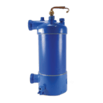
Hydro-Pro - Titanium Heat Exchanger for Inverter 13 Heat Pump - 7021820
941,95 €

Flotide/MEGA - Water Inlet Temperature Sensor TH6 with Plug (6×4) - 7020263
15,95 €

Flotide/MEGA - PP Pipe Plug ½" Male Thread 10 Bar Black - 0121241
3,45 €

Flotide/MEGA - Exhaust Temperature Sensor TH3 with Plug (6×4) - 7020261
15,95 €

Flotide/MEGA - Heat Pump High Pressure Switch 3.6–4.2 MPa - 7024793
21,95 €

Flotide/MEGA - Low Pressure Switch 0.1–0.3 MPa (Heat Pump A3/32) - 7024791
21,95 €

Flotide/MEGA - Low Pressure Switch 0.2–0.35 MPa (Inverter Heat Pump Xp05Csie) - 7024792
21,95 €

Hydro-Pro - Inverter Heat Pump Main Control Board 7 / 10 / 13 kW (53B) - 7020760
559,45 €

Description
Hydro-Pro Heat Pump, Type Inverter (Type Xp13Dcsi+) exploded view & spare parts
This page provides the full exploded-view diagram and numbered bill of materials (BOM) for the Hydro-Pro Heat Pump, Type Inverter — model Xp13Dcsi+, factory reference 7018547. The diagram covers every major assembly and sub-component of this inverter-driven pool heat pump, from the refrigerant circuit and titanium heat exchanger through to the control electronics, fan assembly, and water connections. Whether you are a pool owner carrying out routine maintenance or a technician tracking down a faulty component, the diagram and BOM together will let you identify your exact part within minutes. Use the SKU shown against each position number to order directly from our catalogue with confidence.
How to use the numbered diagram to find your part
Every call-out number printed on the exploded-view diagram corresponds to a row in the parts list below it — locate the area of the unit where the fault or wear is visible, then find the matching position number on the diagram. Once you have the position number, cross-reference it to the BOM row and note the SKU; that SKU is what you add to your basket. Bear in mind that some position numbers appear more than once on the diagram: for example, positions 39 and 46 both describe a Water Connection Set (SKU 7014153), because the same fitting is used at both the inlet and outlet. Similarly, positions 30 and 35 are both labelled “Wiring cover” — check which side of the unit you are working on before ordering. Pay close attention to lettered suffixes: positions such as 23a / 23b, 49 / 49b, 56 / 56b, and 65 / 65b denote alternative variants that are not interchangeable with one another. If a position number in this BOM does not carry a SKU, the component is either part of a larger assembly or is not currently sold separately — contact us before ordering if you are unsure.
Main replaceable assemblies on the Hydro-Pro Inverter Xp13Dcsi+
The air-side assembly (positions 15–19) centres on the fan motor bracket (pos. 15), the 120 W DC fan motor ZWB378D02B (pos. 17, SKU 7021812), and the 496 mm × 150 mm anticlockwise fan blade (pos. 19, SKU 7021815), all of which work together to draw air across the evaporator coil. The evaporator cold-weather protection is handled by the 230 V / 65 W heating belt (pos. 14, SKU 7020272), secured by its clip at position 13, which prevents the evaporator from freezing during low-temperature starts. The refrigerant circuit runs from the compressor (pos. 27) through the 4-way reversing valve (pos. 54), the electronic expansion valve (pos. 63), and the distribution piping (pos. 36, 51–55, 58, 62); the high-pressure switch at pos. 57 (SKU 7024793) and the low-pressure switches at pos. 60 (SKU 7024791) and pos. 61 (SKU 7024792) provide safety cut-outs across this circuit. The titanium heat exchanger (pos. 47, SKU 7021820) is the heart of the water-side circuit, transferring heat to the pool water; it is sealed by the red and blue rubber rings at positions 40 and 48 respectively. Water flow into and out of the heat exchanger is managed through the water connection sets at positions 39 and 46 (both SKU 7014153) and monitored by the water flow switch VH-2 at pos. 42 (SKU 7020257). Temperature sensing across the water circuit is shared between the water-out sensor TH5 (pos. 44, SKU 7020262) and the water-in sensor TH6 (pos. 49, SKU 7020263), while exhaust and ambient/pipe sensing is covered at pos. 56 (SKU 7020261). The control electronics are housed in the electric box (pos. 66) behind the electric box cover (pos. 64); the inverter main board (pos. 65, SKU 7020760) orchestrates compressor speed, fan speed, and defrost logic. The user-facing control interface consists of the waterproof display box (pos. 22, SKU 7010543) fitted with either of the two LED display options at position 23. Cold-weather protection for the compressor itself is provided by the dedicated 230 V / 35 W compressor heating belt (pos. 29, SKU 7020267).
Choosing between variants and pack sizes
Several positions in this BOM come in two distinct variants identified by a plain number and a lettered suffix — these are not interchangeable and you must establish which revision your unit carries before ordering. Position 23a (SKU 7020256) is the standard LED display module (SHHCLEDMM101), while 23b (SKU 7023600) is the Wi-Fi-enabled version (WiFi02iMM011); fitting the wrong display will render the interface non-functional. The same logic applies to the main board at position 65: SKU 7020760 suits the standard Inverter 7/10/13 board, while the 65b variant (SKU 7020771) is specific to the 13(B) revision of the unit and is designed to work in combination with the “B” series sensor sets (positions 44b, 49b, and 56b). For the temperature sensors at positions 44, 49, and 56, the plain-numbered variants and the lettered “b” variants carry different SKUs and different plug configurations — always verify the plug size and pin count on the existing sensor before ordering a replacement. Where the BOM lists a pressure switch, note that positions 60 and 61 cover two different pressure ranges (0.1–0.3 MPa and 0.2–0.35 MPa respectively), so check the rating printed on the original switch body to ensure you select the correct replacement.
