


Flotide/MEGA Heat Pump (Type 3) exploded view & spare parts
 Certified online store
 Easy returns within 14 days


Spare parts list
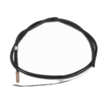
Pipe Temperature Sensor T3 - 7010533
12,45 €

Water Inlet Temperature Sensor T1 for Hydro-Pro Heat Pump - 7010534
10,45 €
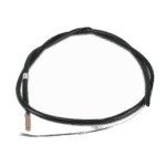
Flotide/MEGA - Water Outlet Temperature Sensor T2 - 7010535
10,45 €

Pool Heat Pump Fan Motor YDK-18-6 18W - 7010520
83,95 €

Motor Fan Blade 320mm × 135mm, 7mm Bore, Counterclockwise - 7010542
15,95 €

Motor Run Capacitor 2 µF Square Plug-in Type - 7010416
3,45 €

Flotide/MEGA - Heat Pump Transformer ZHL-03/EL-48 - 7010532
26,45 €

Flotide/MEGA - Motor Run Capacitor 25µF for SC100 / SC150 Pool Pump - 7010427
57,45 €

Flotide/MEGA - Heat Pump Control Board ZK 101 V13 - 7019176
218,95 €

Flotide/MEGA - Heat Pump Terminal Block 220–240 V / 16 A (10 mm²) - 7010525
20,95 €

Flotide/MEGA - Heat Pump High Pressure Switch 3.6–4.2 MPa - 7024793
21,95 €

Flotide/MEGA - Low Pressure Switch 0.1–0.3 MPa (Heat Pump A3/32) - 7024791
21,95 €

Motor Terminal Block 380–400 V / 16 A - 7010526
6,45 €

Pressure Gauge 0–55 Bar R410A - 7010518
47,45 €
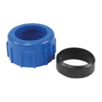
Water Connection 50mm Compression Socket - 7014126
41,95 €

Flotide/MEGA - PP Pipe Plug ½" Male Thread 10 Bar Black - 0121241
3,45 €

Flotide/MEGA - Heat Pump Water Flow Switch with 32 mm Glue Adapter - 7006471
51,45 €

Flotide/MEGA - Heat Pump LED Display Controller XK 302 V1 - 7019178
125,95 €

Description
I have enough context from the BOM and background research. Here is the HTML landing page description:
Flotide/MEGA Heat Pump (Type 3) exploded view & spare parts
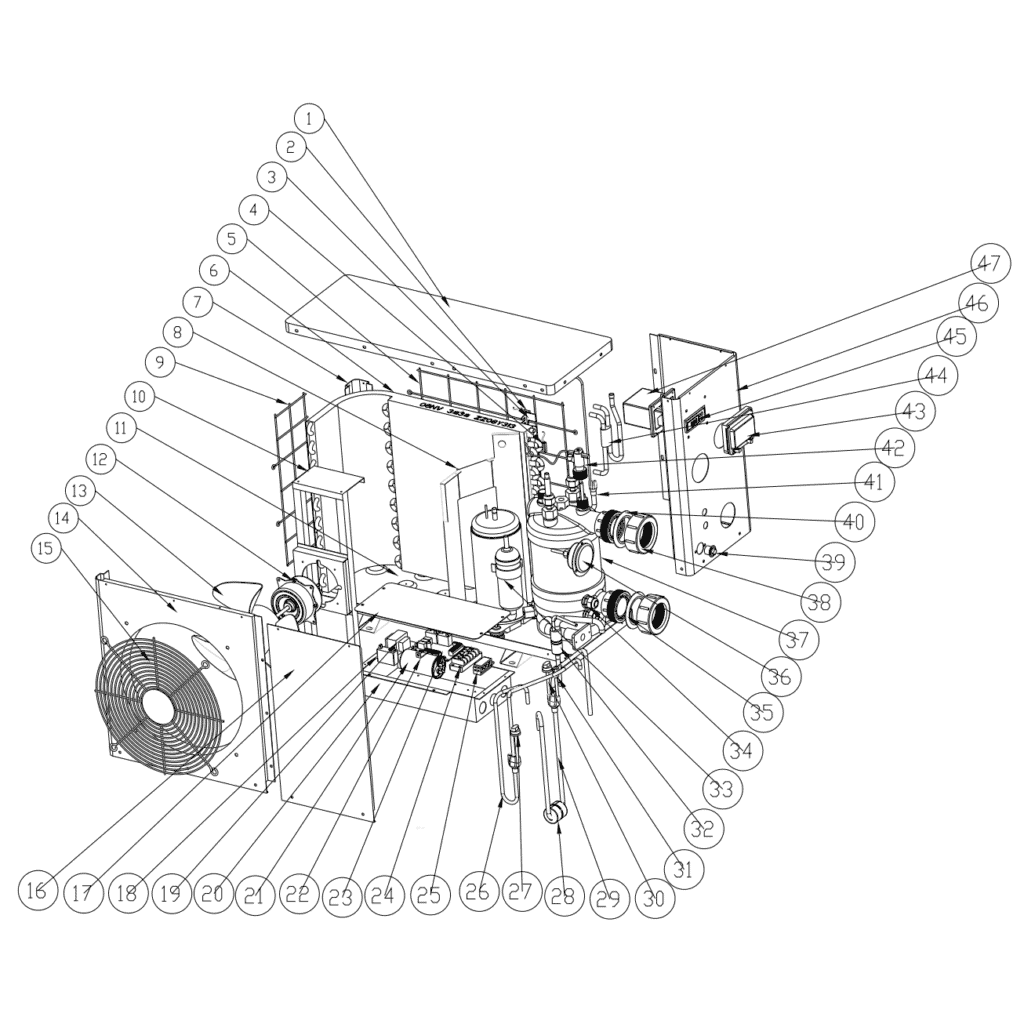
This page provides the official exploded-view diagram and complete bill of materials for the Flotide/MEGA Heat Pump Type 3, referenced under factory number 7018517. The diagram covers every major assembly of the unit, from the refrigerant circuit and electrical enclosure through to the air-handling components and water connections. Whether you are a pool owner carrying out a straightforward sensor swap or a qualified technician overhauling the refrigerant side, the numbered diagram and the parts list below will help you pinpoint the exact component you need. Work through the diagram systematically and you should have your part identified within a few minutes.
How to use the numbered diagram to find your part
Every call-out number printed on the diagram corresponds directly to a numbered row in the parts list table below. The most reliable approach is to start by locating the area of the unit where you suspect the fault — for example, the electrical enclosure, the water circuit, or the air-handling section — and then identify the relevant call-out number in that zone of the diagram. Once you have the number, find the matching row in the table to confirm the description and, where available, note the SKU to use when adding the part to your basket. Pay particular attention to positions that carry a letter suffix: positions 4a, 4b, 4c, and 4d, for instance, all sit within the same sensor group but each refers to a distinct temperature sensor monitoring a different point in the refrigerant or water circuit, so selecting the wrong letter variant will result in an incorrect part being ordered. Some structural positions — such as the motor fixture (pos. 10), base tray (pos. 11), or various panels — do not currently carry a purchasable SKU, meaning those items are not stocked as individual spare parts; if you are unsure whether a part is available, check the SKU column first before contacting us. Finally, verify the description carefully against any label, rating plate, or part number visible on the component you are replacing, since the same assembly position can sometimes accept components with different electrical ratings or physical dimensions depending on the production run.
Main replaceable assemblies on the Flotide/MEGA Heat Pump (Type 3)
The Type 3 is organised into four broad sub-systems, all of which are represented in the diagram. The air-handling section sits at the top of the unit and centres on the fan motor (pos. 12, YDK-18-6 18 W) and the matching fan blade (pos. 13, 320 mm × 135 mm), which draws ambient air across the evaporator (pos. 6) to extract heat. The refrigerant circuit runs from the evaporator through the compressor (pos. 33) and electronic expansion valve (pos. 31), and is safeguarded by a high-pressure switch rated 3.6–4.2 MPa (pos. 27) and a low-pressure switch rated 0.1–0.3 MPa (pos. 30); a pressure gauge (pos. 36) allows on-site monitoring without additional tooling. Heat is transferred to the pool water inside the heat exchanger (pos. 37), and water flow is confirmed by the flow switch with glue adapter (pos. 42) fitted to the distribution pipework. The water connection assembly (pos. 38, 50 mm compression) provides the interface to the pool’s circulation pipework, with the blue and red rubber rings (pos. 35 and 40) providing the seals at each port. The electrical enclosure (pos. 20) houses the primary control board — PC board Flotide/MEGA ZK 101 V13 (pos. 23) — along with the transformer ZHL-03/EL-48 (pos. 19), two capacitors of differing ratings (pos. 18 and pos. 21), and separate terminal blocks for 220–240 V (pos. 24) and 380–400 V (pos. 34) supplies, reflecting that the Type 3 is available in both single-phase and three-phase configurations. User interaction is handled through the LED display Flotide/MEGA XK 302 V1 (pos. 45), which mounts behind the display cover (pos. 47) on the front of the unit.
Choosing between variants and pack sizes
The most important variant group on this diagram is the temperature sensor set at position 4. Although they share a common physical form factor, sensors 4a (pipe temperature T3, SKU 7010533), 4b (water-in temperature T1, SKU 7010534), 4c (water-out temperature T2, SKU 7010535), and 4d (back gas temperature T4, SKU 7010536) are each calibrated and positioned for a specific measurement point; substituting one sensor type for another will cause the control board to read incorrect temperatures and the unit to behave unpredictably. Similarly, the two capacitors in the electrical box are not interchangeable: pos. 18 is a 2 µF square plug-in type (SKU 7010416) used on the fan motor circuit, while pos. 21 is a 25 µF round wired type (SKU 7010427) used on the compressor start circuit — always confirm both the capacitance value and the physical connection type before ordering. The terminal blocks at pos. 24 and pos. 34 differ by voltage rating (220–240 V versus 380–400 V respectively), so confirm your supply voltage before selecting one. Where no SKU is listed against a position, that component is not currently available as a standalone spare; please contact us and we will advise on the best course of action.
