



Flotide/MEGA Heat Pump (Type 10) exploded view & spare parts
 Certified online store
 Easy returns within 14 days


Spare parts list
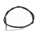
Pipe Temperature Sensor T3 - 7010533
12,45 €

Water Inlet Temperature Sensor T1 for Hydro-Pro Heat Pump - 7010534
10,45 €
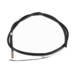
Flotide/MEGA - Water Outlet Temperature Sensor T2 - 7010535
10,45 €

Pool Heat Pump Fan Motor YDK-25-6 25W - 7010521
92,45 €

Flotide/MEGA - Heat Pump Fan Blade 401mm × 119mm, 8mm Bore, Anticlockwise - 7021814
41,95 €

Flotide/MEGA - Heat Pump Transformer ZHL-03/EL-48 - 7010532
26,45 €

Flotide/MEGA - Heat Pump Control Board ZK 101 V13 - 7019176
218,95 €

Motor Run Capacitor 2 µF Square Plug-in Type - 7010416
3,45 €

Flotide/MEGA - Motor Run Capacitor 45µF Round Wired - 7017684
37,95 €

Flotide/MEGA - Heat Pump Terminal Block 220–240 V / 16 A (10 mm²) - 7010525
20,95 €

Flotide/MEGA - Low Pressure Switch 0.1–0.3 MPa (Heat Pump A3/32) - 7024791
21,95 €

Flotide/MEGA - Heat Pump High Pressure Switch 3.6–4.2 MPa - 7024793
21,95 €
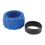
Water Connection 50mm Compression Socket - 7014126
41,95 €

Pressure Gauge 0–55 Bar R410A - 7010518
47,45 €

Flotide/MEGA - PP Pipe Plug ½" Male Thread 10 Bar Black - 0121241
3,45 €

Motor Terminal Block 380–400 V / 16 A - 7010526
6,45 €
Motor Terminal Block 380–400 V / 16 A - 7010526
6,45 €

Flotide/MEGA - Heat Pump Water Flow Switch with 32 mm Glue Adapter - 7006471
51,45 €

Flotide/MEGA - Heat Pump LED Display Controller XK 302 V1 - 7019178
125,95 €

Description
Flotide/MEGA / MEGA Heat Pump (Type 10) exploded view & spare parts
This page provides the full exploded-view diagram and bill of materials for the Flotide/MEGA / MEGA Heat Pump (Type 10), sold under factory reference 7018520. The diagram covers every major sub-assembly of the unit — from the refrigerant circuit and electrical box through to the water connections and control display. Whether you are a pool owner carrying out routine maintenance or a technician diagnosing a fault, you will be able to match the numbered call-out on the diagram to the correct spare part within minutes. All orderable parts carry a SKU that can be placed directly into the search bar or basket on poolparthub.com.
How to use the numbered diagram to find your part
Every number printed on the exploded-view diagram corresponds to a row in the parts list below the image; locating the right component is a matter of finding it visually on the diagram, noting its position number, and then looking up that number in the table to retrieve the SKU. Start by identifying the general area of the unit where your faulty or worn component sits — for example, the electrical box area, the refrigerant pipework, or the water connection side — then scan that region of the diagram for the relevant call-out number. Bear in mind that some position numbers carry letter suffixes: positions 8a, 8b, 8c and 8d all refer to temperature sensors within the same sensor family, so you must confirm which sensor location (pipe, water-in, water-out, or back-gas) matches your requirement before ordering. It is also worth noting that positions 41 and 42 share the same description and SKU — both are 380–400 V / 16 A terminal blocks — which is common where identical components appear in two separate locations inside the electrical box. If a row in the parts list shows no SKU, that component is a structural or sheet-metal part not currently stocked as an individual spare; contact our team if you need guidance on sourcing those items. Always cross-reference the position number shown on the physical unit or in your original documentation with the diagram number, as third-party diagrams occasionally use different numbering schemes.
Main replaceable assemblies on the Flotide/MEGA / MEGA Heat Pump (Type 10)
The fan and airflow assembly is one of the most frequently serviced areas of this unit: position 14 is the YDK-25-6 25 W fan motor, and position 15 is the matched fan blade (401 × 119 mm, 8 mm bore, anticlockwise rotation) — these two parts must be compatible with each other, so if you are replacing the blade alone, confirm the bore size and rotation direction before ordering. The electrical box (position 13) houses the majority of the control and power components: the Flotide/MEGA ZK 101 V13 PC board at position 20, the ZHL-03/EL-48 transformer at position 19, a 2 µF square plug-in capacitor at position 21, and a larger 45 µF round wired capacitor at position 23. The display and user interface is centred on the Flotide/MEGA XK 302 V1 LED display at position 47, housed within its waterproof box (position 46) and display cover (position 48). The refrigerant circuit includes the compressor (position 34), the evaporator (position 10), the electronic expansion valve (position 29), the return pipe (position 30), and the exhaust pipe (position 32); safety on this circuit is provided by the low pressure switch at position 28 (rated 0.1–0.3 MPa, SKU 7024791) and the high pressure switch at position 31 (rated 3.6–4.2 MPa, SKU 7024793). On the water-side, the heat exchanger at position 36 transfers heat to the pool water; flow is monitored by the water flow switch with glue adapter (32 mm) at position 45, and pool pipework connects via the 50 mm compression water connection set at position 38. Sealing integrity across the water circuit is maintained by the blue rubber ring (position 37) and red rubber ring (position 43). Temperature monitoring throughout the refrigerant and water circuits is handled by the four sensors at positions 8a–8d: the pipe temperature sensor T3 (SKU 7010533), water-in sensor T1 (SKU 7010534), water-out sensor T2 (SKU 7010535), and back-gas sensor T4 (SKU 7010536).
Choosing between variants and pack sizes
The most important variant group on this unit is the temperature sensor set at positions 8a, 8b, 8c and 8d. Although all four sensors may look similar physically, each is calibrated or positioned for a specific circuit point — T1 monitors incoming water temperature, T2 monitors outgoing water temperature, T3 monitors refrigerant pipe temperature, and T4 monitors back-gas temperature — so ordering the wrong suffix will result in incorrect readings and possible fault codes. The two terminal blocks also merit attention: position 26 is rated for 220–240 V / 16 A with a 10 mm² conductor rating, while positions 41 and 42 are rated for 380–400 V / 16 A; fitting the lower-voltage block in a three-phase position, or vice versa, would create a safety hazard. Similarly, the capacitors at positions 21 and 23 differ significantly in capacitance (2 µF versus 45 µF) and in their connection type (square plug-in versus round wired), so confirm both the capacitance value and the connector format before ordering. When in doubt about any variant, the SKU shown in the parts table is the definitive reference — quoting it directly when contacting our support team will ensure you receive exactly the correct component.
