



Hydro-Pro Heat Pump, Type Z Inverter (Type Z29/32) exploded view & spare parts
 Certificado tienda en línea
 Devoluciones fáciles dentro de 14 días


Lista de piezas de repuesto

Hydro-Pro - Banda calefactora para evaporador 230 V, 65 W, 2000 mm - 7020274
58,95 €

Hydro-Pro - Heat Pump Fan Motor ZWB378D02B 120W - 7021812
414,45 €

Hydro-Pro - Inverter Heat Pump Fan Blade 496mm × 150mm, 12mm Bore, Anticlockwise - 7021815
80,95 €

Flotide/MEGA - Inverter Heat Pump LED Display SHHCLEDV2MM101 - 7021826
226,95 €

Hydro-Pro - Compressor Crankcase Heating Belt 230V 35W 430mm - 7025155
47,95 €

Flotide/MEGA - Manómetro para refrigerante, 63 mm, 0–65 bar, R32, conexión trasera de 1/4" - 7025310
46,45 €

Flotide/MEGA - Low Pressure Switch 0.1–0.3 MPa (Heat Pump A3/32) - 7024791
21,95 €

Flotide/MEGA - Heat Pump High Pressure Switch 3.6–4.2 MPa - 7024793
21,95 €

Flotide/MEGA - Exhaust Temperature Sensor TH3 with Plug (6×4) - 7020261
15,95 €

Flotide/MEGA - Water Flow Switch with VH-2 Plug (9×7 mm) - 7020257
100,95 €

Flotide/MEGA - Water Outlet Temperature Sensor TH5 with Plug (6×4) - 7020262
15,95 €

Hydro-Pro - Titanium Heat Exchanger for Inverter Type Z29/32 Heat Pump - 7025167
815,95 €
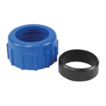
Water Connection 50mm Compression Socket - 7014126
41,95 €

Flotide/MEGA - Water Inlet Temperature Sensor TH6 with Plug (6×4) - 7020263
15,95 €

Flotide/MEGA - PP Pipe Plug ½" Male Thread 10 Bar Black - 0121241
3,45 €

Hydro-Pro - Inverter Driver Board IBQ050R3A (Type Z29/32) - 7025160
479,45 €

Hydro-Pro - Placa de filtro HMF1W-1A para bomba de calor con inversor tipo Z29/32 - 7025312
466,95 €
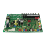
Hydro-Pro - Main Control Board IB050R3A (HWM1W-6B01) for Type Z Inverter Heat Pump Z29/32 - 7025159
714,95 €

Descripción
Hydro-Pro Heat Pump, Type Z Inverter (Type Z29/32) exploded view & spare parts
This page contains the official exploded-view diagram and full bill of materials for the Hydro-Pro Heat Pump, Type Z Inverter, covering the Z29/32 model variant (Hydro-Pro factory reference 7024522). The Type Z Inverter series is a variable-capacity R32 pool heat pump built around an ABS cabinet, a titanium heat exchanger, and an inverter-driven compressor and fan motor — components that are reflected directly in the numbered positions of this diagram. Whether you are carrying out routine maintenance or replacing a failed component after a fault code, the diagram and parts list below will help you identify the exact part you need in minutes. If you already know your position number from the unit’s service manual, you can go straight to the table and search by that number.
Cómo utilizar el esquema numerado para localizar tu pieza
Every numbered call-out bubble on the diagram corresponds to exactly one row in the parts table below — locate your area of interest on the unit (for example, the electrical enclosure or the refrigerant circuit), find the call-out number in that area, then look up that number in the table to retrieve the description and, where available, the SKU you need to add to your basket. Read the description carefully before ordering: some position numbers share the same label in different locations on the unit — positions 15 and 39, for example, are both described as “Clip” and serve different roles in the assembly, so confirm which area of the machine you are working on before selecting one. Pay particular attention to lettered variants: position 26 exists as 26a (LED display, SKU 7021826) and 26b (Colour TFT display, SKU 7025263), which are two entirely different display boards that are not interchangeable. Similarly, positions 73, 74, and 80 are listed as N/A in this revision of the diagram, meaning those slots are not populated on the Z29/32 build; do not assume a part exists for those numbers. If a position has no SKU listed, the component is not currently sold separately — contact our team for guidance on assembly-level replacements.
Main replaceable assemblies on the Hydro-Pro Type Z Inverter (Z29/32)
El air-side circuit centres on the fan motor at position 18 (ZWB378D02B 120W, SKU 7021812) and the fan blade at position 19 (496 mm × 150 mm, 12 mm hole, anticlockwise rotation, SKU 7021815); both must be matched to each other and to the DC motor casing tube at position 20. Wrapped around the evaporator coil is the evaporator heating belt at position 16 (230 V 65 W 2000 mm, SKU 7020274), which prevents frost damage during low-ambient operation. The refrigerant circuit is the heart of the machine: the inverter-driven compressor sits at position 29 (MVB33FBPMC), protected by its own heating belt at position 32 (230 V 35 W 430 mm, SKU 7025155) and cushioned by the anti-vibration hammer at position 30. Refrigerant flow is directed by the 4-way valve at position 51, metered by the electronic expansion valve at position 57, and passes through the filter at position 58 and the liquid reservoir at position 31 before reaching the heat exchanger. Circuit integrity is monitored by the low pressure switch at position 47 (0.1–0.3 MPa, SKU 7024791) and the high pressure switch at position 52 (3.6–4.2 MPa, SKU 7024793), with the exhaust temperature sensor at position 53 (TH3, SKU 7020261) providing additional protection. The water-side circuit passes through the titanium heat exchanger at position 63 (specific to the Z29/32 build, SKU 7025167); water flow is verified by the flow switch at position 60 (VH-2, SKU 7020257), and water temperatures are measured at the outlet by sensor TH5 at position 61 (SKU 7020262) and at the inlet by sensor TH6 at position 67 (SKU 7020263). The R32 refrigerant circuit is also fitted with a pressure gauge at position 38 (0–65 bar, SKU 7025310). The electronics enclosure (electric box, position 78) houses the main board at position 77 (HWM1W-6B01 IB050R3A, SKU 7025159), the driver board at position 72 (HMD1W-6AA00 IBQ050R3A, SKU 7025160), and the filter board at position 75 (HMF1W-1A, SKU 7025312) — the three boards that govern inverter operation and should be diagnosed systematically before replacing any one of them.
Choosing between variants and pack sizes
The most important variant choice on this diagram is the display board at position 26: 26a is the standard LED display (SHHCLEDV2MM101, SKU 7021826), while 26b is the Colour TFT display for the Z Series (TSiV1, SKU 7025263). These boards use different connectors and firmware interfaces, so you must match the replacement to whichever display type was originally fitted to your unit — check the label on the existing board before ordering. For the water connection set at position 64, note that the listed part (SKU 7014126) is a 50 mm compression-type fitting specified for ECO and Flotide/MEGA connections; if your pipework uses a different diameter or joining method, verify compatibility before purchasing. Sensor plugs also carry size references in their descriptions (for example, the 6×4 mm plug shared by sensors at positions 53, 61, and 67, versus the 9×7 mm plug of the flow switch at position 60) — these plug dimensions must match the corresponding socket on the controller board to ensure a reliable connection. Where a position has no SKU, the component is not available as an individual spare in the current catalogue; in those cases, please use the enquiry form on the product page and quote the factory reference 7024522 along with the position number so our team can advise on the best course of action.
