



Pompa de căldură Flotide/MEGA, tip inverter (model Xp06Csie) – vedere explodată și piese de schimb
 Certificat magazin online
 Retururi ușoare în termen de 14 zile


Lista pieselor de schimb

Flotide/MEGA - Senzor de temperatură ambientală TH1 cu conector tip mufă (6×4) - 7020259
15,95 €
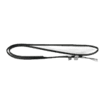
Flotide/MEGA - Senzor de temperatură pentru conducte TH2 cu conector 6×4 - 7020260
12,45 €

Motor ventilator pentru pompă de căldură pentru piscină YDK-25-6 25 W - 7010521
92,45 €

Pală ventilator pentru pompă de căldură pentru piscină, 400 mm × 118 mm, orificiu de 8 mm, rotație în sens invers acelor de ceasornic - 7010538
31,45 €

Flotide/MEGA - Cutie de afișaj rezistentă la apă pentru pompă de căldură cu invertor (tip Xp05Csie) - 7010543
31,45 €

Flotide/MEGA - Afișaj LED pentru pompă de căldură cu invertor SHHCLEDV2MM101 - 7021826
226,95 €

Flotide/MEGA - Panou de afișare cu LED-uri și Wi-Fi pentru pompă de căldură cu invertor (WiFi02iMM011) - 7023600
252,45 €

Manometru 0–55 bar R410A - 7010518
47,45 €

Flotide/MEGA - Senzor de temperatură a apei la intrare TH6 cu conector (6×4) - 7020263
15,95 €

Flotide/MEGA – Schimbător de căldură din titan pentru pompa de căldură Hydro-S Inverter 6 – 7021845
567,95 €

Flotide/MEGA - Dop pentru țeavă din PP, filet exterior de ½", 10 bari, negru - 0121241
3,45 €

Flotide/MEGA - Senzor de temperatură a apei la ieșire TH5 cu mufă (6×4) - 7020262
15,95 €

Flotide/MEGA - Comutator de debit de apă cu mufă VH-2 (9×7 mm) - 7020257
100,95 €

Flotide/MEGA - Senzor de temperatură a gazelor de eșapament TH3 cu conector (6×4) - 7020261
15,95 €

Flotide/MEGA - Comutator de înaltă presiune pentru pompă de căldură 3,6–4,2 MPa - 7024793
21,95 €

Flotide/MEGA - Comutator de presiune joasă 0,1–0,3 MPa (Pompă de căldură A3/32) - 7024791
21,95 €

Flotide/MEGA - Comutator de presiune joasă 0,2–0,35 MPa (pompă de căldură cu invertor Xp05Csie) - 7024792
21,95 €

Flotide/MEGA - Placă de comandă pentru pompă de căldură cu invertor SH0150101-V1.5 - 7021834
559,45 €

Condensator de funcționare pentru motor, 2 µF, tip cu conector pătrat – 7010416
3,45 €

Flotide/MEGA - Curea pentru încălzitorul carterului compresorului 230 V, 35 W, 340 mm - 7020267
44,45 €

Descriere
Flotide/MEGA Heat Pump Inverter (Type Xp06Csie) exploded view & spare parts
This page provides the full exploded-view diagram and numbered bill of materials for the Flotide/MEGA Heat Pump, Type Inverter, model reference Xp06Csie (factory assembly reference 7021085). The diagram covers every major sub-assembly of the unit — from the refrigerant circuit and fan section through to the electrical box and water connections — giving pool owners and technicians a single reference point for the entire machine. Identify the area of the unit that needs attention, locate the corresponding position number on the diagram, and match it to the parts list below to find the correct SKU. In most cases you will have the right part identified within a few minutes.
Cum să folosiți schema numerotată pentru a găsi piesa dorită
Every numbered call-out printed on the diagram corresponds directly to a row in the parts list table; the position number is your primary key for cross-referencing. Start by identifying the general area of the unit where your fault or wear has occurred — for example, the water circuit at the rear, the fan assembly at the top, or the electrical box on the right-hand side — then scan that region of the diagram for the relevant call-out numbers. Once you have a position number, find the matching row in the table to retrieve the SKU you need to order. Bear in mind that some generic hardware items, such as clips, appear more than once in the diagram at different locations: positions 7 and 25 are both listed as “Clip”, so confirm which physical location on the unit you are working on before ordering. Similarly, piping runs appear at multiple positions (31 and 32, and further refrigerant lines at positions 51 through 58), so trace the pipe carefully on the diagram rather than assuming all pipe entries are identical. Pay close attention to lettered variants: position 28 splits into 28a and 28b, which are two distinct LED display boards — make sure you have noted the correct suffix before proceeding. Where a position has no SKU shown, that component is either not sold separately or is currently unlisted; contact us if you need guidance on those items.
Main replaceable assemblies on the Flotide/MEGA Xp06Csie
The fan section sits at the top of the unit and centres on the YDK-25-6 25 W fan motor (position 13, SKU 7010521) mounted to its bracket (position 12) and driving a 400 mm × 118 mm eight-blade fan with an 8 mm anti-clockwise bore (position 14, SKU 7010538); both the motor and blade are available as individual spare parts. Ambient conditions are monitored by the ambient temperature sensor at position 2 (SKU 7020259), which clips into its retainer at position 3 alongside the sensor casing pipe at position 8. The refrigerant circuit is the heart of the machine: the evaporator (position 10) draws heat from the air, the compressor (position 19) raises refrigerant pressure, and the four-way valve (position 46) manages the heating and defrost cycles; refrigerant pressures are protected by a high-pressure switch rated 3.6–4.2 MPa (position 49, SKU 7024793) and two low-pressure switches — one rated 0.1–0.3 MPa (position 50, SKU 7024791) and one rated 0.2–0.35 MPa (position 55, SKU 7024792). An electronic expansion valve at position 54 controls refrigerant flow, while the exhaust temperature sensor TH3 at position 47 (SKU 7020261) and the pipe temperature sensor TH2 at position 6 (SKU 7020260) feed real-time data to the control board. The water side of the unit features a titanium heat exchanger (position 36, SKU 7021845), which transfers heat to pool water; water inlet temperature is measured by sensor TH6 at position 34 (SKU 7020263), water outlet temperature by sensor TH5 at position 44 (SKU 7020262), and flow confirmation is provided by the water flow switch VH-2 at position 45 (SKU 7020257). Water connections are made via the water connection sets at positions 40 and 41 (both SKU 7014153), sealed with the O-type ring at position 38, the blue rubber ring at position 39, and the red rubber ring at position 42. The electrical box (position 64) houses the main PC board SH0150101-V1.5 (position 60, SKU 7021834), a 2 µF square plug-in capacitor (position 61, SKU 7010416), magnetic rings at positions 62 and 63, and the reactor/PFC conductor at position 30; the waterproof display box (position 27, SKU 7010543) and its LED display board mount externally. A compressor heating belt rated 230 V 35 W 340 mm (position 65, SKU 7020267) protects the compressor during cold-weather standby periods, and a pressure gauge (position 29, SKU 7010518) allows on-site monitoring of refrigerant pressure.
Alegerea între variante și dimensiunile ambalajelor
The most important variant choice on this unit is at position 28, where the LED display board is listed as either 28a (SHHCLEDV2MM101, SKU 7021826) or 28b (WiFi02iMM011, SKU 7023600). These are two electrically distinct boards — 28a is the standard inverter display, while 28b is the Wi-Fi-enabled version — and they are not interchangeable, so you must confirm which board your unit was originally fitted with before ordering. The easiest way to verify this is to check the label on the existing board or review your original purchase documentation. For the temperature sensors at positions 2, 6, 34, 44, and 47, each is listed with a 6×4 plug specification; all five are sold as individual sensors with their own SKUs, so order only the specific sensor corresponding to the position number you have identified on the diagram rather than buying the full set unnecessarily. The water connection sets at positions 40 and 41 share the same SKU (7014153), confirming they are identical items — if both inlet and outlet connections need replacing, simply order a quantity of two. For sealing components such as the O-type ring (position 38), blue rubber ring (position 39), and red rubber ring (position 42), these are colour-coded for a reason: each sits in a specific location within the water circuit and has a distinct geometry, so take care to replace like-for-like using the diagram to confirm the correct position before ordering.
