



Bomba de calor Hydro-Pro, inversor Tipo Z (Tipo Z11/32) — vista explodida e peças sobressalentes
 Certificado loja online
 Devoluções fáceis em até 14 dias


Lista de peças sobressalentes

Flotide/MEGA - Sensor de temperatura ambiente TH1 com conector de ficha (6×4) - 7020259
15,95 €

Hydro-Pro - Motor do ventilador da bomba de calor ZWB378D02B 120 W - 7021812
414,45 €

Hydro-Pro - Pá de ventilador para bomba de calor com inversor, 496 mm × 150 mm, orifício de 12 mm, rotação no sentido anti-horário - 7021815
80,95 €

Flotide/MEGA - Ecrã LED para bomba de calor com inversor SHHCLEDV2MM101 - 7021826
226,95 €

Flotide/MEGA - Cinta de aquecimento do cárter do compressor 230 V, 35 W, 390 mm - 7020268
43,95 €

Flotide/MEGA - Manómetro para refrigerante, 63 mm, 0–65 bar, R32, ligação traseira de 1/4" - 7025310
46,45 €
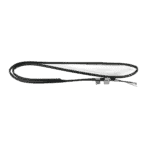
Flotide/MEGA - Sensor de temperatura para tubos TH2 com ficha 6×4 - 7020260
12,45 €

Flotide/MEGA - Interruptor de alta pressão para bomba de calor 3,6–4,2 MPa - 7024793
21,95 €

Flotide/MEGA - Interruptor de baixa pressão 0,1–0,3 MPa (Bomba de calor A3/32) - 7024791
21,95 €

Flotide/MEGA - Sensor de temperatura dos gases de escape TH3 com conector (6×4) - 7020261
15,95 €
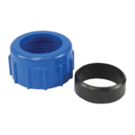
Racorde de compressão para ligação de água de 50 mm - 7014126
41,95 €

Flotide/MEGA - Interruptor de fluxo de água com ficha VH-2 (9×7 mm) - 7020257
100,95 €

Flotide/MEGA - Sensor de temperatura de saída de água TH5 com ficha (6×4) - 7020262
15,95 €

Hydro-Pro - Permutador de calor em titânio para bomba de calor com inversor do tipo Z11/32 - 7025162
529,95 €

Flotide/MEGA - Sensor de temperatura da água de entrada TH6 com ficha (6×4) - 7020263
15,95 €

Flotide/MEGA - Tampão para tubo de PP com rosca macho de ½", 10 bar, preto - 0121241
3,45 €

Hydro-Pro - Placa de controlo principal da bomba de calor com inversor IB015R3A (Tipo Z7/32 e Z11/32) - 7025156
575,45 €

Descrição
Hydro-Pro Heat Pump Type Z Inverter (Type Z11/32) exploded view & spare parts
This page provides the full exploded-view diagram and bill of materials for the Hydro-Pro Heat Pump Type Z Inverter, model Z11/32, com referência de fábrica 7024516. The Type Z Inverter is a horizontal, R32-refrigerant pool heat pump whose inverter-driven compressor and fan vary their speed continuously to match heating demand, keeping noise low and efficiency high. Every numbered position in the diagram below corresponds directly to a row in the parts list, so you can pinpoint the component you need and, where a spare part is stocked, proceed straight to its SKU. Most owners or technicians working from a faulty component or a service manual can identify their part in just a few minutes using this reference.
Como utilizar o esquema numerado para encontrar a sua peça
Start by locating the area of the unit where the fault or wear has occurred — for example, the refrigerant circuit, the water circuit, the fan assembly, or the electrical enclosure. Once you have identified the general zone, trace the call-out lines in the diagram to find the position number that points to your component. Every position number in the diagram matches a row in the parts table below; the row will show you the full description and, where available, the SKU you need to add to your basket. Bear in mind that positions 10, 11, e 66 are listed as N/A in this diagram — these numbers are reserved in the factory sequence but do not correspond to a separately orderable part on the Z11/32. Pay particular attention to lettered variants: position 20 splits into 20a e 20b, which are two entirely different display assemblies; fitting the wrong one will render the control system inoperable, so check your existing display type before ordering. Finally, note that some small hardware items such as clips (positions 3, 31, 38) and sealing rings (positions 54, 55, 56) may look interchangeable but are specified to exact dimensions in the factory drawing — always cross-reference the full description, not just the position number.
Main replaceable assemblies on the Hydro-Pro Heat Pump Type Z Inverter (Type Z11/32)
O fan and air-side assembly occupies the upper section of the unit and centres on the fan motor ZWB378D02B 120W (pos. 12, SKU 7021812) mounted on its bracket (pos. 8) inside the DC motor casing tube (pos. 14). The motor drives a fan blade measuring 496 mm × 150 mm with a 12 mm anti-clockwise bore (pos. 15, SKU 7021815) — the rotation direction and bore size are critical, so confirm both before ordering. Air drawn through the back grill (pos. 4) passes over the evaporator (pos. 6), which transfers heat from the ambient air into the refrigerant circuit. The circuito de refrigerante is anchored by the inverter compressor SVB140FCAMC (pos. 26), supported on anti-vibration hammers (pos. 25) and kept warm during cold starts by the compressor heating belt 230V 35W 390 mm (pos. 24, SKU 7020268). Refrigerant flow is managed by the 4-way valve (pos. 47), o electronic expansion valve (pos. 49), and monitored by the high-pressure switch 3.6–4.2 MPa (pos. 42, SKU 7024793) e o low-pressure switch 0.1–0.3 MPa (pos. 43, SKU 7024791); the pressure gauge 0–65 bar R32 (pos. 29, SKU 7025310) provides a visual reference during servicing. The circuito de água runs through the titanium heat exchanger Z11/32 (pos. 59, SKU 7025162), which is the core of pool water heating, with flow confirmed by the water flow switch VH-2 (pos. 53, SKU 7020257) and connections made via the water connection set 50 mm compression type (pos. 52, SKU 7014126). Five temperature sensors report back to the main board: TH1 ambient (pos. 2, SKU 7020259), TH2 pipe (pos. 39, SKU 7020260), TH3 exhaust (pos. 45, SKU 7020261), TH5 water out (pos. 57, SKU 7020262), e TH6 water in (pos. 61, SKU 7020263). O caixa elétrica abriga o main board HWM1W-5FA01 IB015R3A (pos. 64, SKU 7025156) inside the electric box (pos. 65) behind its cover (pos. 63), with the reactor (pos. 9), terminal board (pos. 28), and magnetic rings (pos. 67, 68) completing the electrical assembly.
Escolher entre variantes e tamanhos de embalagem
The most consequential variant choice on this diagram is the display assembly at position 20. Position 20a (SKU 7021826) is the standard LED display identified as SHHCLEDV2MM101, whilst position 20b (SKU 7025263) is the upgraded colour TFT display identified as TSiV1, specific to the Z series. These two displays use different communication protocols with the main board — fitting the TFT display to a unit wired for the LED version, or vice versa, will result in a non-functional control panel, so inspect your existing display or consult your original purchase documentation before selecting. Apart from the display, the sensor plugs at positions 2, 39, 45, 57, and 61 all share the same 6×4 mm plug format but carry different factory SKUs because each sensor is calibrated to a specific measurement range and point in the refrigerant or water circuit; they are not interchangeable even though they look identical. Similarly, the water flow switch at position 53 uses a distinct 9×7 mm plug and must not be substituted with a 6×4 mm sensor. When ordering sealing components such as the red rubber ring (pos. 54), O-ring (pos. 55), or the sealing ring for the water flow switch (pos. 56), check the diameter and cross-section against your existing part, as minor dimensional differences can result in refrigerant or water leaks.
