



Pompa ciepła Hydro-Pro, typ inwerterowy (typ Xp35Dcsi+) – widok rozłożony i części zamienne
 Certyfikowany sklep internetowy
 Łatwe zwroty w ciągu 14 dni


Lista części zamiennych

Hydro-Pro – Taśma grzewcza do parownika 230 V, 65 W, 2000 mm – 7020274
58,95 €

Hydro-Pro – Silnik wentylatora pompy ciepła YDK-50-8GXX 50 W – 7021813
260,95 €

Hydro-Pro – Łopatka wentylatora do pompy ciepła 490 mm × 125 mm, otwór 12 mm, obrót zgodny z ruchem wskazówek zegara – 7010540
36,95 €

Flotide/MEGA – Wodoodporna obudowa wyświetlacza do pompy ciepła z falownikiem (typ Xp05Csie) – 7010543
31,45 €

Hydro-Pro – Sterownik wyświetlacza LED do pomp ciepła z falownikiem SHHCLEDMM101 – 7020256
226,95 €

Flotide/MEGA – panel wyświetlacza LED z modułem Wi-Fi do pompy ciepła z inwerterem (WiFi02iMM011) – 7023600
252,45 €

Hydro-Pro – Pasek grzewczy do skrzyni korbowej sprężarki 230 V, 35 W, 430 mm – 7020270
58,95 €

Manometr 0–55 bar R410A – 7010518
47,45 €

Hydro-Pro – zestaw czujników temperatury otoczenia/rurociągu/spalin TH3/TH5/TH6 z wtyczką 16×4 – 7020266
47,45 €

Flotide/MEGA – Przełącznik wysokiego ciśnienia do pomp ciepła 3,6–4,2 MPa – 7024793
21,95 €

Flotide/MEGA – przełącznik niskiego ciśnienia 0,1–0,3 MPa (pompa ciepła A3/32) – 7024791
21,95 €

Flotide/MEGA – przełącznik niskiego ciśnienia 0,2–0,35 MPa (pompa ciepła z falownikiem Xp05Csie) – 7024792
21,95 €

Hydro-Pro – przełącznik przepływu wody z wtykiem XH-2 (6×4 mm) – 7020258
100,95 €
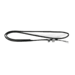
Hydro-Pro – Czujnik temperatury wody na wlocie TH1 z wtykiem (6×4) – Falownik Xp26Dcsi+ – 7020264
15,95 €

Hydro-Pro – tytanowy wymiennik ciepła do pompy ciepła Inverter 26 / 26T – 7021823
1.421,45 €

Hydro-Pro – Czujnik temperatury wody na wylocie TH2 z wtykiem (6x4) – 7020265
15,95 €

Flotide/MEGA – zatyczka do rur PP, gwint zewnętrzny ½", 10 bar, czarna – 0121241
3,45 €

Hydro-Pro – płytka sterownika falownika 26T/35T
2.174,45 €

Przekaźnik stycznikowy CJX9B-25S/D 220–240 V AC do pompy ciepła Eco 12 – 7010519
142,95 €
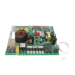
Hydro-Pro – główna płytka sterująca do pompy ciepła do basenu z falownikiem 26T – 7020764
744,45 €

Opis
Hydro-Pro Heat Pump, Type Inverter (Type XP35DCSI+) exploded view & spare parts
Na tej stronie zamieszczono pełny rysunek rozłożony oraz listę materiałów do Hydro-Pro Heat Pump, Type Inverter (Type XP35DCSI+), identified under factory reference 7018552. The diagram covers every major assembly and sub-component of this inverter-technology pool heat pump, from the refrigerant circuit and titanium heat exchanger through to the electronic control boards and display panels. The Hydro-Pro Inverter range uses a variable-speed compressor and fan motor to vary heating output according to ambient conditions, making precise part identification especially important when servicing. Using the numbered diagram alongside the parts list below, you should be able to pinpoint the exact component you need in just a few minutes.
Jak skorzystać z numerowanego schematu, aby znaleźć potrzebną część
Every call-out number printed on the exploded-view diagram corresponds directly to a numbered row in the parts list table below the image. Start by locating the general area of the unit where your fault or wear has occurred — for example, the refrigerant circuit at the rear, the electrical box on the right side, or the water connections and heat exchanger section — then trace the relevant call-out number within that area. Once you have the position number, find the matching row in the parts list; if a SKU is shown, that part is available to order directly. Be aware that some position numbers appear more than once on the diagram because the same component is used in multiple locations — position 63 and position 70, for instance, both refer to the same water connection set (SKU 7014153) fitted at the inlet and outlet respectively. Pay close attention to lettered suffixes: positions 27a oraz 27b share the same physical location on the diagram but refer to two different LED display variants, so selecting the wrong letter will result in an incompatible board being ordered. Where no SKU is listed against a position number, the part is either a structural panel or a refrigerant-circuit pipe assembly that is not supplied as a standalone spare; in such cases, please contact us before ordering. Always cross-reference the factory reference number 7018552 if you are unsure whether a part shown belongs to this specific model.
Main replaceable assemblies on the Hydro-Pro Heat Pump, Type Inverter (Type XP35DCSI+)
Ten zespół po stronie lotniskowej sits at the top of the unit and centres on the fan motor (position 19, SKU 7021813), a YDK-50-8GXX 50 W unit mounted via the fan motor bracket (position 18) and motor tube (position 20). The fan blade at position 21 (SKU 7010540) is a 490 mm × 125 mm clockwise-rotation blade with a 12 mm bore, and must be matched precisely to the motor to maintain correct airflow over the evaporator. Wrapped around the evaporator is the pas grzewczy parownika (position 17, SKU 7020274), a 230 V / 65 W / 2000 mm frost-protection element held in place by the clip at position 16 — this is a common service item during winter commissioning. The obieg chłodniczy runs from the compressor (position 31) through the 4-way valve (position 55), electronic expansion valve (position 49), fluid reservoir (position 32), filter (position 48), and the various interconnecting pipe assemblies at positions 50–52 and 60–62. Protecting the high side of the circuit is the przełącznik wysokiego ciśnienia (position 54, SKU 7024793, rated 3.6–4.2 MPa), while the low side carries one of two pressure switches — position 58 (SKU 7024791, 0.1–0.3 MPa) or position 59 (SKU 7024792, 0.2–0.35 MPa) — depending on the specific build variant. The obieg wodny connects to the pool via the water connection sets at positions 63 and 70 (both SKU 7014153), with the water flow switch at position 66 (SKU 7020258) monitoring flow and the titanium heat exchanger at position 72 (SKU 7021823) transferring heat to the pool water. Temperature monitoring across the water circuit is handled by the inlet sensor TH1 at position 68 (SKU 7020264) and the outlet sensor TH2 at position 73 (SKU 7020265). The skrzynka elektryczna (position 83) houses the inverter driver board at position 76 (SKU 7020768), the main inverter board at position 80 (SKU 7020764), and the relay at position 77 (SKU 7010519), all of which are serviceable items. The compressor is protected by its own frost-protection heating belt at position 33 (SKU 7020270), a 230 V / 35 W / 430 mm element that is considerably shorter than the evaporator belt and must not be substituted with it. A set of three temperature sensors covering ambient, pipe, and exhaust (TH3/TH5/TH6) is supplied together at position 53 (SKU 7020266) as a matched plug assembly.
Wybór między wariantami a rozmiarami opakowań
Najważniejszy wybór wariantu na tym schemacie znajduje się w punkcie position 27, where 27a and 27b designate two distinct LED display boards for the inverter control system: the SHHCLEDMM101 (SKU 7020256) and the WiFi02iMM011 (SKU 7023600). These are not interchangeable — selecting the wrong variant will result in a display that does not communicate with the main board. Check your existing display’s model code, printed on the board itself, before ordering. A similar consideration applies to the two low-pressure switches at positions 58 and 59: although they look identical externally, their calibrated operating ranges differ (0.1–0.3 MPa versus 0.2–0.35 MPa), and fitting the wrong rating can cause nuisance trips or, conversely, fail to protect the compressor. For the heating belts, positions 17 and 33 are both 230 V elements but differ in wattage and length — 65 W / 2000 mm for the evaporator and 35 W / 430 mm for the compressor — so always order by position number rather than by specification alone. Where sealing consumables such as the O-ring (position 65) or the blue and red rubber rings (positions 64 and 71) are concerned, verify the diameter against the mating connection before fitting, as the water connection sets at positions 63 and 70 share the same SKU but are installed at different points in the water circuit.
