



Pompa ciepła Flotide/MEGA, typ inwerterowy (typ Xp20Csie) – widok rozłożony i części zamienne
 Certyfikowany sklep internetowy
 Łatwe zwroty w ciągu 14 dni


Lista części zamiennych

Flotide/MEGA – Czujnik temperatury otoczenia TH1 z złączem wtykowym (6×4) – 7020259
15,95 €
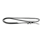
Flotide/MEGA – Czujnik temperatury rurowej TH2 z wtykiem 6×4 – 7020260
12,45 €
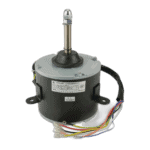
Flotide/MEGA – Silnik wentylatora YDK-70-8GXX 70 W – 7019179
355,95 €

Hydro-Pro – Łopatka wentylatora do pompy ciepła 490 mm × 125 mm, otwór 12 mm, obrót zgodny z ruchem wskazówek zegara – 7010540
36,95 €

Flotide/MEGA – Pas grzewczy do skrzyni korbowej sprężarki 230 V, 35 W, 320 mm – 7020269
45,45 €

Manometr 0–55 bar R410A – 7010518
47,45 €

Flotide/MEGA – Wodoodporna obudowa wyświetlacza do pompy ciepła z falownikiem (typ Xp05Csie) – 7010543
31,45 €

Flotide/MEGA – Wyświetlacz LED do pompy ciepła z inwerterem SHHCLEDV2MM101 – 7021826
226,95 €

Flotide/MEGA – Czujnik temperatury spalin TH3 z wtykiem (6×4) – 7020261
15,95 €

Flotide/MEGA – Przełącznik wysokiego ciśnienia do pomp ciepła 3,6–4,2 MPa – 7024793
21,95 €

Flotide/MEGA – przełącznik niskiego ciśnienia 0,1–0,3 MPa (pompa ciepła A3/32) – 7024791
21,95 €

Flotide/MEGA – przełącznik niskiego ciśnienia 0,2–0,35 MPa (pompa ciepła z falownikiem Xp05Csie) – 7024792
21,95 €

Flotide/MEGA – Czujnik temperatury wody na wylocie TH5 z wtyczką (6×4) – 7020262
15,95 €

Flotide/MEGA – Czujnik temperatury wody na wlocie TH6 z wtyczką (6×4) – 7020263
15,95 €

Flotide/MEGA – tytanowy wymiennik ciepła do pompy ciepła Hydro-S Inverter 20 – 7021848
1.265,95 €

Flotide/MEGA – zatyczka do rur PP, gwint zewnętrzny ½", 10 bar, czarna – 0121241
3,45 €

Flotide/MEGA – Przełącznik przepływu wody z wtykiem VH-2 (9×7 mm) – 7020257
100,95 €

Flotide/MEGA - Inverter Heat Pump PC Board SH0300101-V1.5 - 7021836
1.101,95 €

Opis
Flotide/MEGA Heat Pump Inverter (Type Xp20Csie) exploded view & spare parts
This page provides the full exploded-view diagram and numbered bill of materials (BOM) for the Flotide/MEGA Swimming Pool Heat Pump, Inverter type, model designation Xp20Csie, covered by factory reference 7021089. The diagram shows every serviceable component in its assembled relationship, from the outer casing panels and fan assembly right through to the refrigerant circuit, heat exchanger, and control electronics. Whether you are a pool owner carrying out routine maintenance or a technician tracing a fault, cross-referencing the diagram with the parts list below will have you identifying the correct part within minutes. All position numbers used on this page correspond directly to those printed on the factory diagram.
Jak skorzystać z numerowanego schematu, aby znaleźć potrzebną część
Start by locating the area of the unit where the fault or wear has occurred — for example, the water connections, the fan assembly, or the controller housing — then scan the diagram for the call-out number closest to that component. Every number in the diagram maps to exactly one row in the parts list, where you will find the part description and, where available, the PoolPartHub SKU ready to add to your basket. Work from the general area of the unit to the specific number, then use the SKU to confirm you have the right item before ordering. Bear in mind that some position numbers appear in more than one location on the diagram: position 7 and position 27, for instance, both refer to a generic clip used at different points in the assembly, so check which physical location matches your need. Similarly, position 68 and position 69 both describe a magnetic ring at two separate locations on the wiring loom. Pay particular attention to positions carrying a letter suffix — position 31a and position 31b cover two distinct display variants for this model — and selecting the wrong variant will result in an incompatible part. If a position number in the BOM has no SKU listed, that component is not currently sold separately; in those cases please contact us and we will advise on the best course of action.
Main replaceable assemblies on the Flotide/MEGA Xp20Csie
The Xp20Csie is an inverter-driven pool heat pump, meaning its compressor and fan speeds vary continuously to match heating demand, which places particular wear patterns on certain components over time. The zespół wentylatora — comprising the fan motor (pos. 14, YDK-70-8GXX 70W) and the 490 mm fan blade (pos. 15) mounted within the fan motor bracket (pos. 13) — is one of the most frequently serviced areas, as the motor runs whenever the unit is operating. The obieg chłodniczy runs from the compressor (pos. 19), through the 4-way valve (pos. 36), the evaporator (pos. 5), and the electronic expansion valve (pos. 51), continuing via the titanium heat exchanger (pos. 55) and back through the liquid reservoir (pos. 22) and filter (pos. 45); the titanium exchanger in particular is a stocked spare (SKU 7021848) owing to its direct contact with pool water. Pressure and safety switching is handled by the high-pressure switch at pos. 41 and two low-pressure switch variants at pos. 42 and pos. 43, all of which are individually available. The temperature sensing circuit includes five plug-type sensors: ambient temperature sensor TH1 (pos. 2, SKU 7020259), pipe temperature sensor TH2 (pos. 6, SKU 7020260), exhaust temperature sensor TH3 (pos. 38, SKU 7020261), water-out sensor TH5 (pos. 52, SKU 7020262), and water-in sensor TH6 (pos. 54, SKU 7020263) — all using the same 6×4 plug format. The water connection interface at the heat exchanger includes the water inlet nut (pos. 57, SKU 7014153), the water outlet nut (pos. 60, SKU 7014153), and the water flow switch (pos. 63, SKU 7020257), along with associated sealing rings at pos. 58, 59, 61, and 62. The control and display system consists of the main PC board SH0300101-V1.5 (pos. 66, SKU 7021836), housed in the controller box (pos. 67) behind its cover (pos. 64), paired with the waterproof display box (pos. 30, SKU 7010543) and the display module at pos. 31a or 31b depending on variant. Finally, the pas grzewczy sprężarki at pos. 21 (230 V, 35 W, 320 mm, SKU 7020269) protects the compressor during cold-start conditions and is a low-cost preventive replacement item worth checking on older units.
Wybór między wariantami a rozmiarami opakowań
The most important variant decision on this diagram is the display module at position 31: pos. 31a is the LED Inverter display (SHHCLEDV2MM101, SKU 7021826), while pos. 31b refers to a WiFi-capable controller display for which no separate SKU is currently listed — if your unit carries the WiFi controller, please contact us before ordering to confirm availability. The two low-pressure switches at pos. 42 and pos. 43 look externally similar but are rated to different pressure ranges (0.1–0.3 MPa and 0.2–0.35 MPa respectively); fitting the wrong switch will affect the unit’s low-pressure cut-out behaviour, so always verify the rating printed on the original component before selecting a replacement. The water inlet nut (pos. 57) and water outlet nut (pos. 60) share the same SKU (7014153), confirming they are identical parts, but note that the associated rubber sealing rings — blue at pos. 58 for the inlet side and red at pos. 61 for the outlet side — are colour-coded for a reason and should be replaced on the correct side to maintain a proper seal. When replacing any sensor from the TH1–TH6 range, double-check the plug format (6×4 on all five sensors listed here) against the socket on your control board, as other variants within the wider Flotide/MEGA range may use a different plug size.
