



Hydro-Pro-warmtepomp, type Z Inverter (type Z7/32) – opengewerkte tekening en reserveonderdelen
 Gecertificeerd webwinkel
 Eenvoudig retourneren binnen 14 dagen


Lijst met reserveonderdelen

Flotide/MEGA - Omgevingstemperatuursensor TH1 met stekkerverbinding (6×4) - 7020259
15,95 €
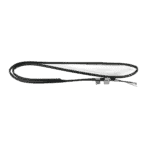
Flotide/MEGA - Leidingtemperatuursensor TH2 met 6×4-stekker - 7020260
12,45 €

Hydro-Pro - Ventilatormotor voor warmtepomp WZD-25 25 W - 7021811
310,45 €

Flotide/MEGA - Ventilatorblad voor warmtepomp 401 mm × 119 mm, asgat 8 mm, tegen de klok in - 7021814
41,95 €

Flotide/MEGA - LED-display voor inverter-warmtepomp SHHCLEDV2MM101 - 7021826
226,95 €

Flotide/MEGA - Riem voor compressor-carterverwarming 230 V, 35 W, 340 mm - 7020267
44,45 €

Flotide/MEGA - Koelmiddeldrukmeter 63 mm 0–65 bar R32 Aansluiting aan de achterzijde 1/4" - 7025310
46,45 €

Flotide/MEGA - Lagedrukschakelaar 0,1–0,3 MPa (warmtepomp A3/32) - 7024791
21,95 €

Flotide/MEGA - Uitlaatgastemperatuursensor TH3 met stekker (6×4) - 7020261
15,95 €

Flotide/MEGA - Hogedrukschakelaar voor warmtepompen 3,6–4,2 MPa - 7024793
21,95 €

Flotide/MEGA - PP-buisplug ½" buitendraad 10 bar zwart - 0121241
3,45 €

Flotide/MEGA - Watertoevoertemperatuursensor TH6 met stekker (6×4) - 7020263
15,95 €

Hydro-Pro - Titanium warmtewisselaar voor inverter-warmtepomp Z7/32 - 7025161
384,95 €
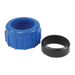
Wateraansluiting 50 mm met knelkoppeling - 7014126
41,95 €

Flotide/MEGA - Temperatuursensor voor wateruitlaat TH5 met stekker (6×4) - 7020262
15,95 €

Flotide/MEGA - Waterstroomschakelaar met VH-2-stekker (9×7 mm) - 7020257
100,95 €

Hydro-Pro - Hoofdbesturingskaart voor inverter-warmtepomp IB015R3A (type Z7/32 en Z11/32) - 7025156
575,45 €

Beschrijving
Hydro-Pro-warmtepomp, type Z Inverter (type Z7/32) – opengewerkte tekening en reserveonderdelen
Op deze pagina vindt u de volledige exploded view en de genummerde stuklijst (BOM) voor de Hydro-Pro Heat Pump, Type Z Inverter, model Z7/32, met Hydro-Pro-fabrieksreferentie 7024515. The Z7/32 is the entry-level model in the Type Z Inverter series — a single-phase, 220–240 V, 50 Hz inverter-driven pool heat pump with a twist-titanium heat exchanger and R32 refrigerant circuit. The diagram covers every major assembly from the outer casing panels and fan section through to the refrigerant pipework, electrical box, and water-side components. Whether you are a pool owner carrying out routine maintenance or a technician tracing a fault to its source, the diagram and the parts list below will help you identify the exact component you need in a matter of minutes.
Hoe u het genummerde schema kunt gebruiken om uw onderdeel te vinden
Every circled number in the exploded-view diagram corresponds directly to a numbered row in the parts table beneath it — locate the area of the unit where the part sits, find the call-out number on the diagram, then match that number to the same position number in the table to retrieve the SKU. Work methodically by section: start with the broad area (for example, the water-side connections at the bottom of the unit, or the electrical box on the front), narrow down to the specific component, then confirm the description matches what you can see on your machine before adding the SKU to your basket. Bear in mind that some generic hardware items — clips, rubber rings, and O-rings — appear at several locations around the unit, so the position number is the only reliable way to distinguish which instance you need. Pay particular attention to lettered variants: positions 20a en 20b are two different display assemblies that share the same location but are not interchangeable, and ordering the wrong one will result in a part that does not connect to your control board. If a position number has no SKU listed, that component is not currently sold individually; in that case, please use the live chat or contact form to ask our team about availability or a suitable assembly-level replacement.
Main replaceable assemblies on the Hydro-Pro Type Z Inverter (Z7/32)
De luchtzijde sits at the top and rear of the cabinet. It comprises the evaporator (pos. 5), which extracts heat from ambient air, and the fan assembly — the WZD-25 25 W fan motor (pos. 13, SKU 7021811) draws air across the evaporator fins, driven by the 401 mm × 119 mm anticlockwise fan blade (pos. 15, SKU 7021814). The ambient air temperature sensor TH1 (pos. 2, SKU 7020259) and its clip (pos. 3) are mounted in this airstream and feed real-time data to the control board. The koelcircuit runs through the heart of the unit: the inverter-driven compressor SVB110FHDMC (pos. 24) is protected by a 230 V 35 W compressor heating belt (pos. 23, SKU 7020267) to prevent cold-start damage, and circuit pressures are monitored by the low-pressure switch (pos. 41, SKU 7024791, rated 0.1–0.3 MPa), the high-pressure switch (pos. 45, SKU 7024793, rated 3.6–4.2 MPa), and the R32 pressure gauge (pos. 31, SKU 7025310). The exhaust temperature sensor TH3 (pos. 42, SKU 7020261) monitors discharge gas temperature on the compressor outlet. The water-side section is centred on the twist-titanium heat exchanger, specific to the Z7/32 (pos. 51, SKU 7025161), through which pool water is circulated. Water inlet temperature is measured by sensor TH6 (pos. 49, SKU 7020263), water outlet temperature by TH5 (pos. 56, SKU 7020262), and the pipe temperature sensor TH2 (pos. 6, SKU 7020260) monitors the refrigerant-side pipe. Water flow is confirmed by the VH-2 flow switch (pos. 58, SKU 7020257) before the unit is permitted to run; its sealing ring (pos. 57) is a frequent low-cost service item. The plumbing connections are made via the 50 mm compression-type water connection set (pos. 54, SKU 7014126). The elektrische en besturingsgedeelte is housed in the electric box (pos. 60): the main inverter board HWM1W-5FA01 IB015R3A (pos. 62, SKU 7025156) governs all inverter functions, while the display (pos. 20a or 20b, see below) provides the user interface.
Kiezen tussen varianten en verpakkingsgroottes
The most important variant choice on this diagram is at position 20, where two mutually exclusive display assemblies are listed. Position 20a is the LED display module (SHHCLEDV2MM101, SKU 7021826), a standard LED readout used on earlier or base-specification Z-series units. Position 20b is the colour TFT display (TSiV1, SKU 7025263), fitted to units supplied with the upgraded colour-screen interface. These two displays use different connectors and firmware handshakes, so you must confirm which display type is physically installed on your unit before ordering — fitting the wrong variant will result in a non-functional control panel. For the water-connection hardware, positions 52 (O-ring), 53 (blue rubber ring), and 55 (red rubber ring) are separate seal components associated with the heat exchanger and water connections; always replace all seals in a joint at the same time to ensure a reliable, leak-free result. When sourcing sensors — positions 2, 6, 42, 49, and 56 — note that whilst the plug format is listed as 6×4 for all of them, each sensor is calibrated for a specific measurement point (ambient air, pipe, exhaust, water-in, water-out) and the SKUs differ accordingly; never substitute one sensor type for another even if the connectors appear identical.
