



Hydro-Pro-warmtepomp, type Z Inverter (type Z19/32) – opengewerkte tekening en reserveonderdelen
 Gecertificeerd webwinkel
 Eenvoudig retourneren binnen 14 dagen


Lijst met reserveonderdelen

Flotide/MEGA - Omgevingstemperatuursensor TH1 met stekkerverbinding (6×4) - 7020259
15,95 €
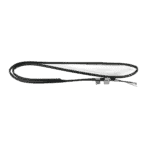
Flotide/MEGA - Leidingtemperatuursensor TH2 met 6×4-stekker - 7020260
12,45 €

Hydro-Pro - Verwarmingsband voor verdamper 230 V 65 W 2000 mm - 7020274
58,95 €

Hydro-Pro - Ventilatormotor voor warmtepomp ZWB378D02B 120 W - 7021812
414,45 €

Hydro-Pro - Vervangingsventilatorblad 554 mm × 148 mm, asgat 10 mm, draait tegen de klok in - 7021816
99,45 €

Flotide/MEGA - LED-display voor inverter-warmtepomp SHHCLEDV2MM101 - 7021826
226,95 €

Hydro-Pro - Verwarmingsriem voor compressorcarter 230 V 35 W 430 mm - 7025155
47,95 €

Flotide/MEGA - Koelmiddeldrukmeter 63 mm 0–65 bar R32 Aansluiting aan de achterzijde 1/4" - 7025310
46,45 €

Flotide/MEGA - Lagedrukschakelaar 0,1–0,3 MPa (warmtepomp A3/32) - 7024791
21,95 €

Flotide/MEGA - Hogedrukschakelaar voor warmtepompen 3,6–4,2 MPa - 7024793
21,95 €

Flotide/MEGA - Uitlaatgastemperatuursensor TH3 met stekker (6×4) - 7020261
15,95 €

Flotide/MEGA - PP-buisplug ½" buitendraad 10 bar zwart - 0121241
3,45 €

Flotide/MEGA - Watertoevoertemperatuursensor TH6 met stekker (6×4) - 7020263
15,95 €
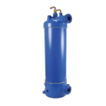
Hydro-Pro - Titanium warmtewisselaar voor warmtepomp van het type Z19/32 met inverter - 7025165
576,45 €
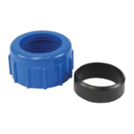
Wateraansluiting 50 mm met knelkoppeling - 7014126
41,95 €

Flotide/MEGA - Temperatuursensor voor wateruitlaat TH5 met stekker (6×4) - 7020262
15,95 €

Flotide/MEGA - Waterstroomschakelaar met VH-2-stekker (9×7 mm) - 7020257
100,95 €

Hydro-Pro - Hoofdbesturingskaart HWM1W-5D00 IB030R3A (omvormer type Z Z19/32 & Z24/32) - 7025158
857,95 €

Beschrijving
Hydro-Pro-warmtepomp, type Z Inverter (type Z19/32) – opengewerkte tekening en reserveonderdelen
Op deze pagina vindt u de volledige exploded view en de stuklijst voor de Hydro-Pro Heat Pump, Type Z Inverter, model Z19/32 — factory reference 7024519. The diagram covers every serviceable position across the entire unit, from the outer casing panels and fan assembly through to the refrigerant circuit, titanium heat exchanger, and electronic control box. It is designed for use with the ABS-bodied, R32-refrigerant, 230 V single-phase variant of the Type Z Inverter range. Whether you are a pool owner carrying out routine sensor maintenance or a qualified technician tracing a fault through the refrigerant or water circuit, you should be able to identify the exact part you need within a few minutes of consulting the diagram alongside this parts list.
Hoe u het genummerde schema kunt gebruiken om uw onderdeel te vinden
Every numbered call-out on the diagram corresponds directly to a row in the parts table below, so the two should always be read together. Start by locating the area of the unit where you observed the fault or wear — for example, the water-side connections at the bottom of the unit, or the fan assembly at the top — then find the matching call-out number on the diagram. Once you have the position number, look up that row in the table to retrieve the SKU, which is what you need to add the correct item to your basket. Bear in mind that a small number of positions — such as clips (pos. 12 and 32) and magnetic rings (pos. 67 and 68) — share the same generic description but appear in different physical locations on the unit; always confirm the location on the diagram before ordering. Pay particular attention to lettered variants: position 22 splits into 22a en 22b, which are two different display assemblies that are not interchangeable. Positions without a SKU listed are structural or refrigerant-circuit components (panels, pipework, valves) that are not individually stocked as retail spare parts; if you require one of these, please contact us directly. Finally, always note any specification detail given in the description — connector pin-counts, voltages, dimensions, and pressure ratings are included precisely because they determine compatibility.
Main replaceable assemblies on the Hydro-Pro Type Z Inverter (Z19/32)
De fan and airside assembly sits at the top of the unit and comprises the fan motor (pos. 15, ZWB378D02B, 120 W) and the fan blade (pos. 16, 554 mm × 148 mm, 10 mm bore, anticlockwise rotation), both of which are individually available as spares. The fan motor is mounted on a dedicated bracket (pos. 14) and draws ambient air across the evaporator (pos. 5); the ambient temperature sensor TH1 (pos. 2) clips to this zone to monitor incoming air conditions. The koelcircuit runs from the compressor (pos. 24, model MVB33FBPMC) through the 4-way valve (pos. 50), the electronic expansion valve (pos. 54), the liquid reservoir (pos. 27), the filter (pos. 45), and a network of interconnecting pipes (pos. 30, 40, 42, 44, 46, 48, 51, 52, 53, 55). Circuit health is monitored by a low-pressure switch (pos. 43, 0.1–0.3 MPa) and a high-pressure switch (pos. 47, 3.6–4.2 MPa), both of which are stocked as individual spare parts, as is the R32 pressure gauge (pos. 33, 0–65 bar). Cold-weather protection for both the evaporator and compressor is provided by heating belts: the evaporator heating belt (pos. 13, 230 V 65 W 2000 mm) and the compressor heating belt (pos. 26, 230 V 35 W 430 mm). The waterzijde-circuit centres on the titanium heat exchanger specific to this model (pos. 61, Z19/32) and is instrumented by three temperature sensors — water-in TH6 (pos. 58), water-out TH5 (pos. 63), and the pipe temperature sensor TH2 (pos. 8) — together with a water flow switch (pos. 65, VH-2). The electronic control system lives in the electric box (pos. 69) and is governed by the main inverter board (pos. 70, HWM1W-5D00 IB030R3A); the exhaust temperature sensor TH3 (pos. 49) monitors discharge-gas temperature at the compressor outlet and is a common service item. The outer structure — top cover (pos. 1), front panel (pos. 18), left panel (pos. 17), right panel (pos. 36), back panel (pos. 41), and back grill (pos. 4) — protects all internal assemblies and is supported by the upper frame (pos. 11) and base tray (pos. 23).
Kiezen tussen varianten en verpakkingsgroottes
De belangrijkste keuze voor een variant op dit diagram is bij position 22, where two mutually exclusive display assemblies are listed: 22a is the LED display (SHHCLEDV2MM101, SKU 7021826) and 22b is the colour TFT display (TSiV1, SKU 7025263). These are different controller interfaces fitted to different production batches of the Z Inverter range; you must match the replacement to the display type already installed on your unit, as they are not electrically or mechanically interchangeable. For the three temperature sensors at positions 2, 8, 49, 58, and 63, all share a 6×4 plug format, while the water flow switch at position 65 uses a 9×7 mm plug — double-checking the connector specification before ordering avoids a wasted return. The compressor heating belt (pos. 26) uses an 8×4 plug, which again differs from the sensor connectors, so connector pin-count is a reliable cross-check. Where description fields include dimensions — such as the fan blade’s 554 mm × 148 mm with a 10 mm bore (pos. 16) — these details exist because even a small deviation in diameter or bore size will prevent correct fitment or produce dangerous imbalance at running speed, so never substitute a nominally similar blade without verifying all three measurements.
