



Hydro-Pro-warmtepomp (type 26) – opengewerkte tekening en reserveonderdelen
 Gecertificeerd webwinkel
 Eenvoudig retourneren binnen 14 dagen


Lijst met reserveonderdelen

Hydro-Pro - LED-bedieningspaneel voor het in- en uitschakelen van warmtepompen XK 001 V1 MM011 - 7010515
168,45 €

Hydro-Pro - WiFi-bedieningspaneel met LED-verlichting voor het in- en uitschakelen van warmtepompen (type WiFi12iMM011) - 7023601
302,95 €
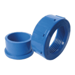
Hydro-Pro - Wateraansluitset 50 mm, lijmmof (set van 2) - 7014127
41,95 €

Manometer 0–55 bar R410A - 7010518
47,45 €
Hydro-Pro - Wateraansluitset 50 mm, lijmmof (set van 2) - 7014127
41,95 €

Hydro-Pro - Titanium warmtewisselaar voor warmtepomp type 26 / 26T (ABS) - 7020789
1.051,45 €

Flotide/MEGA - Waterstroomschakelaar voor warmtepompen met 32 mm lijmadapter - 7006471
51,45 €
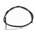
Flotide/MEGA - Temperatuursensor voor wateruitlaat T2 - 7010535
10,45 €

Temperatuursensor T1 voor de watertoevoer van de Hydro-Pro-warmtepomp - 7010534
10,45 €
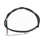
Leidingtemperatuursensor T3 - 7010533
12,45 €
Hydro-Pro - Vervangende printplaat ZK 102 V1 voor warmtepomp type 13 - 7010514
168,45 €

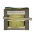
Flotide/MEGA - Warmtepomptransformator ZHL-03/EL-48 - 7010532
26,45 €
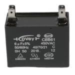
Hydro-Pro - Condensator voor ventilatormotor, 6 µF, vierkant model met stekkerverbinding - 7019180
9,95 €

Hydro-Pro - Condensator voor warmtepompmotor, 80 µF, rond model - 7017453
39,95 €
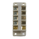
Hydro-Pro - Aansluitblok voor warmtepomp 220–240 V / 32 A (16 mm²) - 7010527
20,95 €

Flotide/MEGA - Lagedrukschakelaar 0,1–0,3 MPa (warmtepomp A3/32) - 7024791
21,95 €

Flotide/MEGA - Hogedrukschakelaar voor warmtepompen 3,6–4,2 MPa - 7024793
21,95 €
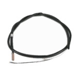
Hydro-Pro warmtepomp-omgevingstemperatuursensor T5 - 7010537
10,45 €

Beschrijving
Hydro-Pro-warmtepomp (type 26) – opengewerkte tekening en reserveonderdelen
Op deze pagina vindt u de volledige exploded view en de stuklijst voor de Hydro-Pro Heat Pump (Type 26), listed under factory reference 7018529. The Type 26 sits at the top of the Hydro-Pro fixed-speed range — an air-source pool heat pump built around a titanium heat exchanger, an ABS cabinet, and an electronic control system designed for extended-season use. Using the numbered diagram below, you can pinpoint every serviceable component, from the control board inside the electric box to the water connection fittings at the plumbing ports. Most visitors locate the part number they need within a few minutes of reading this guide.
Hoe u het genummerde schema kunt gebruiken om uw onderdeel te vinden
Every numbered call-out printed on the diagram corresponds directly to a row in the parts list below it — find the area of the unit that concerns you, note the position number printed on the diagram, then look up that same number in the table to retrieve the description and, where one is assigned, the SKU you will need to add to your basket. Work methodically: start with the broad area (water circuit, refrigerant circuit, electric box, or cabinet panels), narrow down to the sub-assembly, and then confirm the position number before ordering. Be aware that the same SKU can appear against more than one position number — for example, the 50 mm glue-socket water connection set (SKU 7014127) is listed at both position 11 and position 16, because an identical fitting is used at both the inlet and the outlet port; you should order one per port unless you are replacing both simultaneously. Pay close attention to lettered suffixes: positions 10a, 10b, and 10c are three distinct variants of the control display assembly, and positions 51a and 51b are two separate soft-starter components — ordering the wrong letter will result in an incompatible part. Where a position carries no SKU, the component is not currently sold as an individual spare; if you need that item, please contact us before ordering so we can advise on the correct course of action. Finally, confirm your factory reference (7018529) matches the label on your unit before placing any order, as the Type 26 shares visual similarities with smaller models in the same range.
Main replaceable assemblies on the Hydro-Pro Heat Pump (Type 26)
The water circuit is the most frequently serviced area of the Type 26. Water enters and leaves the unit through the 50 mm glue-socket connection sets at positions 11 and 16, sealed by the red rubber (pos. 12) and blue rubber (pos. 17) gaskets respectively. Flow through the unit is monitored by the water flow switch with 32 mm glue adapter at position 19 (SKU 7006471), which automatically enables and disables the compressor depending on whether the pool pump is running. The heart of the heat exchange process is the titanium heat exchanger at position 18 (SKU 7020789); titanium construction makes it resistant to chlorine, salt, and bromine, and it is secured and thermally monitored by the titanium exchanger temperature fixing pieces at positions 20 and 22. Water temperature is tracked at two points: the water-in temperature sensor T1 at position 23 (SKU 7010534) and the water-out temperature sensor T2 at position 21 (SKU 7010535). Ambient air temperature is measured by the ambient temperature sensor T5 at position 59 (SKU 7010537), whilst the refrigerant pipe temperature is monitored by the pipe temperature sensor T3 at position 27 (SKU 7010533). The refrigerant circuit also incorporates the 4-way valve assembly (positions 36, 56, and 57), the electronic expansion valve (pos. 34), and refrigerant pressure protection via the low-pressure switch at position 54a (SKU 7024791, rated 0.1–0.3 MPa) and the high-pressure switch at position 54b (SKU 7024793, rated 3.6–4.2 MPa). The electric box (pos. 37) houses the main PC board ZK 101 V1 at position 39 (SKU 7010514), the transformer ZHL-03/EL-48 at position 40 (SKU 7010532), the AC contactor at position 49, and the terminal block rated 220–240 V / 32 A at position 46 (SKU 7010527); two capacitors are also housed here — the 6 µF square-plug type at position 41 (SKU 7019180) and the 80 µF capacitor at position 43 (SKU 7017453). The system pressure is displayed externally via the pressure gauge at position 14 (SKU 7010518), which is a useful first check when diagnosing refrigerant-side faults.
Kiezen tussen varianten en verpakkingsgroottes
Position 10 splits into three lettered variants — 10a, 10b, and 10c — each representing a different control display or housing option. Position 10a is the standard LED display On/Off unit (XK 001 V1 MM011, SKU 7010515), while position 10b is the WiFi-enabled LED display (type WiFi02iMM101, SKU 7023601); these two panels are electronically different and not interchangeable, so check your existing display’s markings before ordering. Position 10c is the waterproofbox housing that protects the display, and this currently carries no individual SKU. Similarly, position 51 divides into 51a (soft starter) and 51b (soft starter capacity), which are separate components within the soft-start circuit — both must be identified individually before replacement. The pressure switches at positions 54a and 54b are rated to entirely different pressure ranges (0.1–0.3 MPa low-side versus 3.6–4.2 MPa high-side) and must never be substituted for one another, even though they may look similar in the diagram. When ordering water-side fittings such as the 50 mm connection sets at positions 11 and 16, always verify the pipe diameter and connection method (glue socket in this case) against your existing installation to ensure a proper seal.
