



Hydro-Pro-warmtepomp (type 10) – opengewerkte tekening en reserveonderdelen
 Gecertificeerd webwinkel
 Eenvoudig retourneren binnen 14 dagen


Lijst met reserveonderdelen
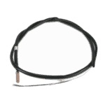
Hydro-Pro warmtepomp-omgevingstemperatuursensor T5 - 7010537
10,45 €

Temperatuursensor T1 voor de watertoevoer van de Hydro-Pro-warmtepomp - 7010534
10,45 €
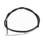
Flotide/MEGA - Temperatuursensor voor wateruitlaat T2 - 7010535
10,45 €

Ventilatormotor voor zwembadwarmtepomp YDK-25-6 25 W - 7010521
92,45 €

Ventilatorblad voor zwembadwarmtepomp 400 mm × 118 mm, asgat 8 mm, draait tegen de klok in - 7010538
31,45 €

Hydro-Pro - LED-bedieningspaneel voor het in- en uitschakelen van warmtepompen XK 001 V1 MM011 - 7010515
168,45 €

Hydro-Pro - WiFi-bedieningspaneel met LED-verlichting voor het in- en uitschakelen van warmtepompen (type WiFi12iMM011) - 7023601
302,95 €

Flotide/MEGA - Warmtepomptransformator ZHL-03/EL-48 - 7010532
26,45 €
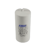
Hydro-Pro - Startcondensator 50 µF, rond, AMP-aansluitingen - 7010432
79,45 €

Motordrijfcondensator 2 µF, vierkant insteektype - 7010416
3,45 €

Hydro-Pro - Printplaat voor warmtepompregeling ZK 101 V1 - 7010513
168,45 €

Flotide/MEGA - Hogedrukschakelaar voor warmtepompen 3,6–4,2 MPa - 7024793
21,95 €

Flotide/MEGA - Lagedrukschakelaar 0,1–0,3 MPa (warmtepomp A3/32) - 7024791
21,95 €
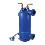
Hydro-Pro - Titanium warmtewisselaar voor warmtepomp type 10 (ABS) - 7020785
403,95 €

Flotide/MEGA - PP-buisplug ½" buitendraad 10 bar zwart - 0121241
3,45 €

Manometer 0–55 bar R410A - 7010518
47,45 €
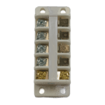
Hydro-Pro - Aansluitblok voor warmtepomp 220–240 V / 32 A (16 mm²) - 7010527
20,95 €

Flotide/MEGA - Waterstroomschakelaar voor warmtepompen met 32 mm lijmadapter - 7006471
51,45 €
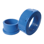
Hydro-Pro - Wateraansluitset 50 mm, lijmmof (set van 2) - 7014127
41,95 €

Beschrijving
Hydro-Pro-warmtepomp (type 10) – opengewerkte tekening en reserveonderdelen
This page contains the official exploded-view diagram and full bill of materials for the Hydro-Pro Heat Pump Type 10 (factory reference 7018524), a 10 kW air-source pool heat pump designed for residential and light-commercial swimming pools. The diagram shows every serviceable component in its correct assembly position, from the refrigerant circuit and electrical enclosure through to the fan, sensors, and water connections. Whether you are a pool owner carrying out routine maintenance or a technician working through a fault-finding procedure, the numbered diagram and parts list below will let you pinpoint the exact component you need in minutes. Use the position numbers printed on the diagram together with the SKU column in the table to place your order directly.
Hoe u het genummerde schema kunt gebruiken om uw onderdeel te vinden
Every numbered call-out on the diagram corresponds to exactly one row in the parts list below — find the number on the drawing and then read across to confirm the description and SKU before adding anything to your basket. The most reliable approach is to work from the general area of the unit (air-side, refrigerant circuit, electrical enclosure, or water connections) down to the specific sub-assembly, and then to the individual position number. Pay close attention to lettered suffixes: position 3, for example, is split into 3a (ambient temperature sensor T5), 3b (water-in sensor T1), 3c (water-out sensor T2), and 3d (pipe sensor T3) — each is a physically different sensor with its own SKU, so selecting the wrong letter will result in an incompatible part being delivered. Similarly, position 15 and position 15b cover two different LED display/controller variants (standard XK 001 V1 and WiFi-enabled WiFi02i), so confirm which display board is fitted to your unit before ordering. Some positions in the diagram — such as structural panels, pipe connections, and covers — do not carry a separate SKU because they are not offered as individual spare parts; these are shown in the list without an order code. If a position you need falls into that category, please contact us for guidance before ordering. Always cross-check the written description against what you can see on the unit, because a number can appear in more than one location on a complex diagram where the same fastener or clip is used in several spots.
Main replaceable assemblies on the Hydro-Pro Heat Pump (Type 10)
The Type 10 is broadly divided into four service areas, each of which groups several numbered positions. The montage aan de luchtzijde handles heat absorption from the ambient air: position 12 is the 400 mm × 118 mm, 8 mm bore anticlockwise fan blade, and position 11 is the YDK-25-6 25 W fan motor that drives it — these two parts work as a pair and are among the most commonly replaced items after a physical impact or bearing failure. The koelcircuit runs through the evaporator (position 7), the compressor (position 34), the 4-way valve (position 33), the electronic expansion valve (position 28), the high-pressure switch rated 3.6–4.2 MPa (position 26, SKU 7024793), the low-pressure switch rated 0.1–0.3 MPa (position 30, SKU 7024791), and the titanium heat exchanger (position 37, SKU 7020785), which transfers heat from the refrigerant into the pool water and is resistant to chlorine and salt. The schakelkast contains the PC board ZK 101 V1 (position 23, SKU 7010513), the transformer ZHL-03/EL-48 (position 19, SKU 7010532), the 50 µF round AMP capacitor (position 20, SKU 7010432), the 2 µF square plugged capacitor (position 22, SKU 7010416), and the LED display/controller panel (position 15 or 15b depending on variant). The water connection area brings pool water in and out of the unit: position 44 is the water flow switch with 32 mm glue adapter (SKU 7006471), which protects the unit from dry running, while position 49 is the water connection set with a 50 mm glue socket (SKU 7014127); the pressure gauge at position 39 (SKU 7010518) and the 32 A / 220–240 V terminal block at position 42 (SKU 7010527) complete the key serviceable items in this zone. The four temperature sensors at positions 3a–3d monitor ambient air, water-in, water-out, and pipe temperatures respectively, feeding data to the control board to regulate operation.
Kiezen tussen varianten en verpakkingsgroottes
The most important variant decision on this unit concerns the control display: position 15 (SKU 7010515) is the standard LED display/On-Off board carrying the reference XK 001 V1 MM011, while position 15b (SKU 7023601) is the WiFi-enabled version carrying the reference WiFi02i MM101 — these are niet interchangeable, so check the label on your existing board or your original purchase documentation before ordering. The four temperature sensors (positions 3a, 3b, 3c, and 3d) each carry a different SKU (7010537, 7010534, 7010535, and 7010533 respectively) and use sensor elements calibrated for different measurement ranges and locations within the refrigerant and water circuit; always match the position letter exactly. For the capacitors, note that position 20 (50 µF, round AMP body, SKU 7010432) and position 22 (2 µF, square plugged body, SKU 7010416) differ in both capacitance and physical form factor — fitting the wrong capacitor can prevent the motor or compressor from starting correctly. The PP plug at position 38 is specified as a ½-inch male thread rated to 10 bar; thread pitch and diameter are fixed by this specification, so do not substitute a metric or BSP fitting without confirming compatibility with your plumbing.
