


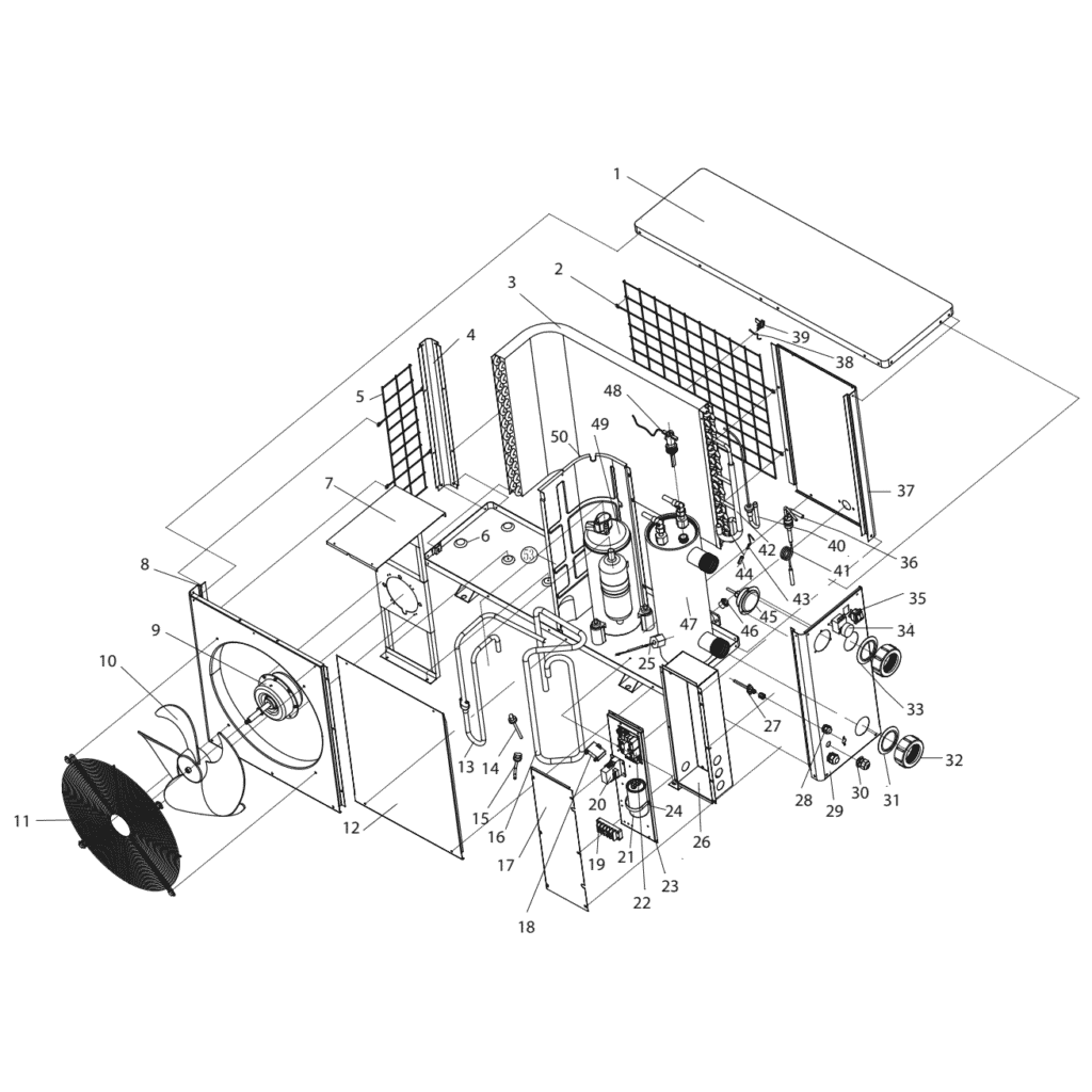
Eco 12 Heat Pump exploded view & spare parts
 Gecertificeerd webwinkel
 Eenvoudig retourneren binnen 14 dagen


Lijst met reserveonderdelen

Ventilatormotor YDK-40-6 40 W voor Eco 12-warmtepomp - 7010522
151,45 €

Ventilatorblad 420 mm × 148 mm, asgat 9 mm, draait met de klok mee - 7010539
43,95 €
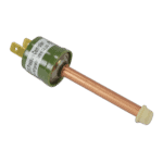
High Pressure Protection Switch 2.9/2.3 MPa (Green) - 7010530
21,95 €
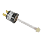
Low Pressure Protection Switch 0.3–0.6 MPa Black - 7010529
21,95 €

Heat Pump Fan Motor Capacitor 3µF Square Plug-In - 7010417
23,95 €

Motor Terminal Block 380–400 V / 16 A - 7010526
6,45 €

Contactor Relay CJX9B-25S/D 220–240 V AC for Eco 12 Heat Pump - 7010519
142,95 €

Motor Run Capacitor 60µF Round AMP - 7010433
39,95 €
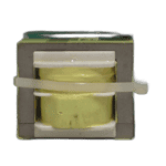
Control Circuit Board ZL 6671 - 7010512
168,45 €
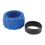
Wateraansluiting 50 mm met knelkoppeling - 7014126
41,95 €

Adjustable Thermostat - 7010517
83,95 €

Mechanical Switch Black/Red - 7010516
41,95 €
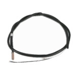
Hydro-Pro Heat Pump Ambient Temperature Sensor T5 - 7010537
10,45 €
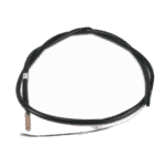
Pipe Temperature Sensor T3 - 7010533
12,45 €

Pressure Gauge 0–55 Bar R410A - 7010518
47,45 €
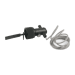
Waterstroomschakelaar voor ECO Hydro-Pro-warmtepomp - 7010531
120,95 €
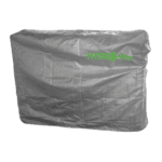
Eco 12 Heat Pump Winter Cover with Side Water Connection Opening 102×32×60 cm - 7009814
69,95 €

Beschrijving
Bosta Eco 12 Heat Pump exploded view & spare parts
This page provides the official exploded-view diagram and full bill of materials for the Bosta Eco 12 swimming pool heat pump, factory reference 7008316. The diagram breaks the unit down into its 50 numbered positions, covering every major assembly from the outer casing and fan section through to the refrigerant circuit, electrical box, and water-side connections. Whether you are a pool owner tracing a fault or a technician ordering a replacement component, the diagram and parts list below allow you to pinpoint the exact part you need in just a few minutes. Where a stockable part has been assigned a SKU by Bosta, that reference is listed directly in the parts table so you can add it to your basket without ambiguity.
Hoe u het genummerde schema kunt gebruiken om uw onderdeel te vinden
Every numbered call-out printed on the exploded-view diagram corresponds directly to a row in the parts list below — locate the area of the unit where your suspect component sits, note its call-out number, then find that number in the “Pos.” column of the table. Once you have matched the position number, the SKU column gives you the exact Bosta part reference to order. Bear in mind that some position numbers in this diagram appear more than once in the table: this occurs where a single diagram call-out covers an assembly that has been assigned its own orderable SKU alongside a descriptive-only row — check both rows carefully before deciding which reference to order. Note also that position 44 is absent from this particular bill of materials, so if you are counting call-outs on the diagram, do not be alarmed by the gap between positions 43 and 45. If you are unsure which of two similarly described parts matches your unit, cross-reference the physical description in the “Description” column — details such as dimensions (for example, the fan blade listed as 420 mm × 148 mm at position 10), capacitor ratings (3 µF at position 18, 60 µF at position 21), or colour coding (blue water inlet bolt at position 31, red outlet bolt at position 33) will help you confirm the correct match before ordering.
Main replaceable assemblies on the Bosta Eco 12
The Eco 12 is an air-source pool heat pump, and its main serviceable sections divide naturally into four areas: the air-side, the refrigerant circuit, the water-side, and the electrical box. On the air side, the fan motor (position 9, rated at 40 W) drives the fan blade (position 10, 420 mm × 148 mm) to draw ambient air across the evaporator coil (position 3); the back grill (position 2) and left grill (position 5) protect this airflow path and are common casualties of impact or UV degradation. The refrigerant circuit runs from the compressor (position 49) through the liquid separator (position 40) and capillary (position 41), with system pressures monitored by the high-pressure protection switch (position 14) and the low-pressure protection switch (position 15); a pressure gauge rated at 5.5 MPa / 100 °C sits at position 45 for service access. Heat is transferred to the pool water through the titanium heat exchanger (position 47), which feeds via the collection pipes (position 42) and the pipe connecting the heat exchanger to the capillary (position 36). Water-side integrity relies on the water flow switch (position 48), which prevents the unit from running dry, along with the water inlet bolt in blue (position 31), the water outlet bolt in red (position 33), and the water connection nut (position 32). The electrical box — protected by covers at positions 17 and 26 — houses the main PC board ZL 6671 (position 22), the AC communicator (position 20), the thermostat (position 34), the mechanical switch (position 35), terminal blocks (position 19), and both the 3 µF capacitor (position 18) for the fan motor and the 60 µF capacitor (position 21) for the compressor. Temperature monitoring is handled by the ambient temperature sensor (position 38) clipped in place by the sensor clip at position 39, and the pipe temperature sensor at position 43.
Choosing between variants and pack sizes
The Bosta Eco 12 bill of materials does not include lettered sub-variants (such as “10a / 10b”) for any position, so each position number maps to a single description — you do not need to choose between size variants within the same call-out number on this model. Where a position carries a specific dimensional or electrical rating, that specification is your primary selection guide: the fan blade at position 10 must match the stated 420 mm diameter and 148 mm pitch, and the two capacitors at positions 18 and 21 must match their respective µF ratings exactly, as substituting an incorrect capacitance will affect motor or compressor start-up performance. For water-connection hardware such as the connection nut at position 32, confirm the thread standard against your existing pipework before ordering, as pool heat pumps may use either metric or BSP thread forms. The isolation panel / winter cover listed at position 50 (SKU 7009814) is a seasonal accessory rather than a consumable spare; if you are ordering it alongside mechanical parts, treat it as a separate line item to avoid confusion with structural casing components at positions 1 through 8.
