



Pompa di calore Hydro-Pro, tipo Inverter (modello Xp07Dcsi+) – vista esplosa e ricambi
 Certificato negozio online
 Resi facili entro 14 giorni


Elenco dei ricambi

Hydro-Pro - Nastro riscaldante per evaporatore 230 V 65 W 1500 mm - 7020271
44,45 €

Hydro-Pro - Motore del ventilatore per pompa di calore WZD-25 25 W - 7021811
310,45 €

Flotide/MEGA - Pala della ventola per pompa di calore 401 mm × 119 mm, foro da 8 mm, rotazione antioraria - 7021814
41,95 €

Flotide/MEGA - Scatola espositiva impermeabile per pompa di calore con inverter (tipo Xp05Csie) - 7010543
31,45 €

Hydro-Pro - Controller con display LED per pompa di calore ad inverter SHHCLEDMM101 - 7020256
226,95 €

Flotide/MEGA - Pannello di visualizzazione a LED con Wi-Fi per pompa di calore con inverter (WiFi02iMM011) - 7023600
252,45 €

Flotide/MEGA - Cinghia per riscaldatore del carter del compressore 230 V 35 W 340 mm - 7020267
44,45 €

Manometro 0–55 bar R410A - 7010518
47,45 €
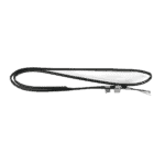
Flotide/MEGA - Sensore di temperatura per tubazioni TH2 con connettore 6×4 - 7020260
12,45 €

Flotide/MEGA - Tappo per tubi in PP, filettatura maschio da ½", 10 bar, nero - 0121241
3,45 €

Flotide/MEGA - Sensore di temperatura dell'acqua in entrata TH6 con connettore (6×4) - 7020263
15,95 €

Hydro-Pro - Scambiatore di calore in titanio per pompa di calore Inverter 7 (XP07DCSI+) - 7021818
559,45 €

Flotide/MEGA - Sensore di temperatura dell'acqua in uscita TH5 con spina (6×4) - 7020262
15,95 €

Flotide/MEGA - Interruttore di flusso dell'acqua con connettore VH-2 (9×7 mm) - 7020257
100,95 €

Hydro-Pro - Scheda di controllo principale per pompa di calore con inverter 7 / 10 / 13 kW (53B) - 7020760
559,45 €

Flotide/MEGA - Pressostato di bassa pressione 0,1–0,3 MPa (pompa di calore A3/32) - 7024791
21,95 €

Flotide/MEGA - Pressostato di bassa pressione 0,2–0,35 MPa (pompa di calore con inverter Xp05Csie) - 7024792
21,95 €

Flotide/MEGA - Pressostato di alta pressione per pompa di calore 3,6–4,2 MPa - 7024793
21,95 €

Flotide/MEGA - Sensore di temperatura dei gas di scarico TH3 con connettore (6×4) - 7020261
15,95 €

Descrizione
Pompa di calore Hydro-Pro, tipo Inverter (modello Xp07Dcsi+) – vista esplosa e ricambi
This page provides the official exploded-view diagram and complete bill of materials (BOM) for the Hydro-Pro Heat Pump, Type Inverter, model designation XP07DCSI+, covered under Hydro-Pro factory reference 7018545. The XP07DCSI+ is a variable-speed inverter pool heat pump whose compressor and fan speeds adjust automatically to suit ambient conditions, keeping running costs and noise to a minimum. Every position number shown on the diagram corresponds directly to a row in the parts table below, so you can move from a failed component to the correct SKU without ambiguity. Most visitors find their part within a few minutes using this diagram.
Come utilizzare lo schema numerato per individuare il proprio componente
Start by locating the area of the unit where the fault or wear is visible — for example, the refrigerant circuit, the water connections, or the electrical enclosure. Each numbered call-out on the diagram (10, 11, 12 … 67) matches exactly one row in the parts list; find that number in the table to read its description and, where available, its SKU for ordering. Some positions carry a lettered suffix — 20a e 20b, for instance, are two distinct LED display variants, and positions 37, 39, 46, e 63 each describe a primary sensor as well as an alternative “B” variant that uses a different plug or sensor set. Always read the full description column, not just the position number, before adding an item to your basket. A handful of positions — such as the clips at positions 26 and 36, and the magnet rings at 50 and 51 — share identical descriptions; confirm their location on the diagram before ordering. Where a position has no SKU listed, that part is not currently stocked as an individual spare; contact us if you need guidance on sourcing those items.
Main replaceable assemblies on the Hydro-Pro Heat Pump, Type Inverter (Type Xp07Dcsi+)
Il circuito del refrigerante forms the heart of the XP07DCSI+. The inverter-driven compressor (pos. 21) is protected by a compressor heating belt (pos. 22, SKU 7020267) that prevents cold-start damage, and its operating pressures are monitored by a low-pressure switch rated 0.1–0.3 MPa (pos. 57, SKU 7024791), a second low-pressure switch rated 0.2–0.35 MPa (pos. 58, SKU 7024792), and a high-pressure switch rated 3.6–4.2 MPa (pos. 61, SKU 7024793). The refrigerant-to-water heat transfer takes place in the scambiatore di calore in titanio (pos. 44, SKU 7021818), with flow controlled and verified by the water flow switch VH-2 (pos. 47, SKU 7020257). On the air side, the fan motor WZD-25 25W (pos. 13, SKU 7021811) drives the fan blade (pos. 15, SKU 7021814 — 401 mm × 119 mm, 8 mm shaft, anticlockwise rotation), both mounted on the fan motor bracket (pos. 12). The evaporator is kept above freezing by its own heating belt (pos. 10, SKU 7020271 — 230 V, 65 W, 1500 mm). Refrigerant flow direction is managed by the four-way valve (pos. 67) and the electronic expansion valve (pos. 56). The main inverter control board (pos. 53, SKU 7020760) sits inside the electric box (pos. 52) and governs the entire system; a variant board for the 7 (B) configuration carries SKU 7020769. The user interface is handled by the waterproof display box (pos. 19, SKU 7010543) together with either the standard LED display (pos. 20a, SKU 7020256) or the Wi-Fi-enabled LED display (pos. 20b, SKU 7023600). Water inlet and outlet connections are sealed with the water connection covers (pos. 43 and 49, both SKU 7014153), colour-coded rubber rings (pos. 42 blue, pos. 48 red), and O-ring seals (pos. 41).
Scelta tra varianti e formati di confezione
Several positions on this diagram exist in two versions, distinguished by a lettered suffix, and selecting the wrong one will result in a non-fitting part. The LED display at position 20a (SKU 7020256) is the standard inverter display module, while position 20b (SKU 7023600) is the Wi-Fi-enabled equivalent — check your existing display before ordering. Sensor positions 37, 39, 46, and 63 each have a primary variant and a “B” variant that differs in plug size or wiring harness configuration; the primary variants use a 6×4 plug, whereas the B variants (for example, pos. 37B and 63B) use a 16×4 plug and are intended to be ordered as a bundled sensor set under SKU 7020266. Similarly, the main board at position 53 has a standard version (SKU 7020760) and a “7 (B)” version (SKU 7020769); if your unit uses any of the B-suffix sensors, it will pair with the B-variant main board. On the pressure-switch side, positions 57 and 58 look physically similar but are calibrated to different switching ranges (0.1–0.3 MPa versus 0.2–0.35 MPa), so always verify the rating printed on your existing switch before selecting a replacement.
