



Norsup Heat Pump, Type Inverter (Type Xp13Dcsi) exploded view & spare parts
 Certificado tienda en línea
 Devoluciones fáciles dentro de 14 días


Lista de piezas de repuesto

Flotide/MEGA - Ambient Temperature Sensor TH1 with Plug Connector (6×4) - 7020259
15,95 €
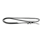
Flotide/MEGA - Pipe Temperature Sensor TH2 with 6×4 Plug - 7020260
12,45 €

Hydro-Pro - Heat Pump Fan Motor ZWB378D02B 120W - 7021812
414,45 €

Hydro-Pro - Inverter Heat Pump Fan Blade 496mm × 150mm, 12mm Bore, Anticlockwise - 7021815
80,95 €

Flotide/MEGA - Waterproof Display Box for Inverter Heat Pump (Type Xp05Csie) - 7010543
31,45 €

Flotide/MEGA - Inverter Heat Pump LED Display SHHCLEDV2MM101 - 7021826
226,95 €

Flotide/MEGA - LED Display Panel with Wi-Fi for Inverter Heat Pump (WiFi02iMM011) - 7023600
252,45 €

Flotide/MEGA - Compressor Crankcase Heater Belt 230V 35W 340mm - 7020267
44,45 €

Pressure Gauge 0–55 Bar R410A - 7010518
47,45 €

Flotide/MEGA - Water Flow Switch with VH-2 Plug (9×7 mm) - 7020257
100,95 €

Flotide/MEGA - Water Outlet Temperature Sensor TH5 with Plug (6×4) - 7020262
15,95 €

Norsup - Titanium Heat Exchanger for Inverter 13 Heat Pump - 7021829
1.026,45 €

Flotide/MEGA - Water Inlet Temperature Sensor TH6 with Plug (6×4) - 7020263
15,95 €

Flotide/MEGA - PP Pipe Plug ½" Male Thread 10 Bar Black - 0121241
3,45 €

Flotide/MEGA - Exhaust Temperature Sensor TH3 with Plug (6×4) - 7020261
15,95 €

Flotide/MEGA - Heat Pump High Pressure Switch 3.6–4.2 MPa - 7024793
21,95 €

Flotide/MEGA - Low Pressure Switch 0.1–0.3 MPa (Heat Pump A3/32) - 7024791
21,95 €

Flotide/MEGA - Low Pressure Switch 0.2–0.35 MPa (Inverter Heat Pump Xp05Csie) - 7024792
21,95 €

Flotide/MEGA - Inverter Heat Pump Control Board SH0200101-V1.5 - 7021835
824,45 €

Descripción
Norsup Heat Pump Inverter (Type Xp13Dcsi) exploded view & spare parts
This page provides the official exploded-view diagram and full bill of materials for the Norsup Heat Pump, Type Inverter — factory reference 7021077, commonly identified by the internal type code Xp13Dcsi. The diagram covers every serviceable component across the airside, refrigerant circuit, waterside, and electrical enclosure of this 230 V full-inverter pool heat pump. Whether you are a pool owner carrying out routine maintenance or a qualified technician tracing a fault, the numbered diagram and the parts list below it will let you pinpoint the exact component you need in a matter of minutes. Cross-referencing the position number with the SKU in the list is all that stands between you and the correct replacement part.
Cómo utilizar el esquema numerado para localizar tu pieza
Every call-out number printed on the exploded-view diagram corresponds directly to a numbered row in the parts table beneath it — locate the area of the heat pump where you are working, find the relevant call-out number on the diagram, then match that number to the same row in the table to retrieve the SKU. Once you have the SKU, you can search or paste it directly into the site search bar to go straight to the correct product listing. Bear in mind that some position numbers carry a letter suffix to denote a variant of the same component: position 21a is the standard LED display (SHHCLEDV2MM101, SKU 7021826) while position 21b is the Wi-Fi-enabled LED display (WiFi02iMM011, SKU 7023600) — you must identify which display your unit was built with before ordering. Not every position in this diagram has a currently stocked spare part; positions shown without a SKU are either non-serviceable sub-assemblies or parts supplied only as part of a larger assembly. Where a position number appears more than once on the diagram — for instance where a clip or sealing ring is used in several locations — always confirm you are reading the correct instance for your area of the unit before noting the position number. If you are unsure whether a part is compatible with your specific serial number or build date, contact our team before ordering.
Main replaceable assemblies on the Norsup Heat Pump Inverter (Type Xp13Dcsi)
The airside of the unit is built around the evaporator (pos. 5), which absorbs heat from the ambient air, and the fan assembly that forces air across it. The fan assembly itself consists of three linked parts: the fan motor ZWB378D02B 120 W (pos. 15, SKU 7021812), its mounting bracket (pos. 13), and the 496 × 150 mm anticlockwise fan blade with a 12 mm bore (pos. 17, SKU 7021815) — all three should be inspected together whenever excessive noise or reduced airflow is reported. The refrigerant circuit is anchored by the compressor (pos. 25), protected during cold periods by the compressor heating belt 230 V 35 W 340 mm (pos. 27, SKU 7020267) and isolated from vibration by the damping feet (pos. 28). Refrigerant flow is metered by the electronic expansion valve (EEV, pos. 50) and regulated between heating and cooling modes by the 4-way valve (pos. 64), with circuit protection provided by the high-pressure switch rated 3.6–4.2 MPa (pos. 56, SKU 7024793) and two low-pressure switch variants — 0.1–0.3 MPa (pos. 59, SKU 7024791) and 0.2–0.35 MPa (pos. 60, SKU 7024792). On the waterside, pool water passes through the titanium heat exchanger (pos. 46, SKU 7021829), which transfers heat from the refrigerant to the pool water; the water flow switch VH-2 (pos. 41, SKU 7020257) guards the unit against running dry. The sensor cluster is a frequent service area: the ambient temperature sensor TH1 (pos. 2, SKU 7020259), pipe temperature sensor TH2 (pos. 6, SKU 7020260), exhaust temperature sensor TH3 (pos. 55, SKU 7020261), water outlet temperature sensor TH5 (pos. 43, SKU 7020262), and water inlet temperature sensor TH6 (pos. 48, SKU 7020263) all use a 6 × 4 plug format and can be replaced individually. The main control electronics are housed behind the electric box cover (pos. 65) and centred on the PC board SH0200101-V1.5 (pos. 66, SKU 7021835), while the user interface is provided by the waterproof display box (pos. 20, SKU 7010543) paired with the relevant LED display at position 21. The pressure gauge (pos. 31, SKU 7010518) and the water connection sets (pos. 38 and pos. 45, both SKU 7014153) are common service items at the waterside connections.
Choosing between variants and pack sizes
The most important variant choice on this diagram is at position 21, where two LED display boards are listed under the same position number: 21a (SKU 7021826, standard inverter display SHHCLEDV2MM101) and 21b (SKU 7023600, Wi-Fi-enabled display WiFi02iMM011). These are not interchangeable without also verifying compatibility with the PC board at position 66, so check your existing display type — usually visible on a label on the board itself — before ordering. The water connection sets at positions 38 and 45 share the same SKU (7014153), confirming they are identical components used at both the inlet and outlet; if both connections are degraded it is sensible to order two units in a single transaction. For sealing components such as the O-type sealing ring (pos. 40), the red rubber ring (pos. 39), and the blue rubber ring (pos. 47), verify the exact internal diameter and cross-section against your existing part before ordering, as these dimensions are not always visible in the diagram alone. The plug at position 49 is specified as PP, ½-inch male thread, 10 bar rated — confirming that thread standard and pressure rating are critical selection criteria that must match your pipework exactly.
