



Hydro Pro Heat Pump Type PX17/32 exploded view & spare parts
 Certificado tienda en línea
 Devoluciones fáciles dentro de 14 días


Lista de piezas de repuesto

Hydro-Pro - Black Glass Control Display CM404 - 7029494
285,45 €

Hydro-Pro - Axial Fan Motor 75W ZWS75-A - 7024943
315,45 €

Hydro-Pro - Heat Pump Top Lid 1002 x 396 mm (PX17/32) - 7033051
105,45 €

Hydro-Pro - Heat Pump Low Pressure Switch 0.3 MPa / 0.15 MPa - 7011009
27,95 €
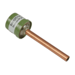
Hydro-Pro - High Pressure Switch 3.2 MPa / 4.4 MPa (Green) for Type P Heat Pump - 7011008
27,95 €

Flotide/MEGA - Heat Pump Water Flow Switch with 32 mm Glue Adapter - 7006471
51,45 €

Hydro-Pro - Panel-Mount Refrigerant Pressure Gauge 0–55 bar R32 - 7026259
44,95 €

Hydro-Pro - Titanium Heat Exchanger for Inverter Heat Pump P13X/32 & PIV 17/32 - 7024945
619,95 €

Descripción
Hydro Pro Heat Pump Type PX17/32 exploded view & spare parts
This page provides the official exploded-view diagram and numbered bill of materials (BOM) for the Bosta Hydro Pro Heat Pump Type PX17/32, factory reference 7028286. The PX17/32 is a horizontal-discharge inverter heat pump that uses R32 refrigerant and a variable-speed Mitsubishi scroll compressor (position 29), making it suitable for year-round pool heating. Whether you are a pool owner carrying out routine maintenance or a technician sourcing a specific component after a fault, this diagram covers every serviceable part of the unit. Work through the numbered call-outs below and you will identify the exact part you need within minutes.
Cómo utilizar el esquema numerado para localizar tu pieza
Every numbered call-out printed on the exploded-view diagram corresponds directly to a row in the parts table beneath it; the position number is your primary reference, not the written description. Start by identifying the area of the unit where the fault or wear has occurred — for example, the air-side (fan and evaporator area), the refrigerant circuit, or the electrical enclosure — then scan that section of the diagram for the relevant call-out number. Once you have the number, find the matching row in the BOM and note the SKU; that SKU is what you add to your basket. Bear in mind that some components appear in more than one location on the diagram: fasteners, brackets, and general hardware can share a single position number even though they are fitted in several places, so always count the quantity you need before ordering. Also note that position 33 bundles several accessory items within a single row — read the full description carefully, as individual sub-items within that entry carry their own separate part numbers (for example, the 10 m extension cable and housing listed as SKU 7029497). If a position in your diagram carries a lettered suffix (such as 10a or 10b), treat each letter as a distinct part with its own dimensions; ordering the wrong lettered variant is the most common cause of a part arriving that does not fit. Positions marked with no SKU in this table are structural or refrigerant-circuit components that are not sold individually as service parts; if you believe one of those items is faulty, please contact us before ordering.
Main replaceable assemblies on the Hydro Pro Heat Pump Type PX17/32
The air-handling assembly sits at the top of the unit and is centred on the axial fan motor (position 6, SKU 7024943, rated 75 W, model ZWS75-A) and the matched fan blade (position 4, SKU 7024944, 510 mm × 160 mm diameter with a 10 mm anti-clockwise shaft bore). The plastic fan net (position 3) and fan protection net (position 8) shield the blade on both the inlet and outlet sides. The glass display panel (position 2, SKU 7029494, CM404) provides the user interface on the front frame (position 1) and is one of the more commonly replaced items after accidental impact or moisture ingress. The top lid (position 12, SKU 7033051, 1002 × 396 mm) seals the cabinet and is available as a standalone spare. Moving into the refrigerant circuit, the titanium heat exchanger (position 27, SKU 7024945, referenced as PIV 17/32) is the core water-side component; titanium construction makes it resistant to pool-chemical corrosion, but it remains a serviceable replacement part. Refrigerant-side safety and control is handled by the low-pressure switch (position 15, SKU 7011009, set at 0.3 MPa / 0.15 MPa) and the high-pressure switch (position 17, SKU 7011008, set at 3.2 MPa / 4.4 MPa), while the pressure gauge (position 24, SKU 7026259) covers 0–55 bar for the R32 refrigerant down to −15 °C. Water-side flow protection is provided by the water flow switch (position 18, SKU 7006471), which prevents the unit running without adequate circulation. The centralized controller board (position 30, SKU 7029488, referencing Bosta codes 82300052 + 82400021 for PIV 17/32) governs the inverter logic and is the primary electrical board to check when the unit displays fault codes or fails to start.
Choosing between variants and pack sizes
The PX17/32 BOM includes temperature sensors that, although printed within position 17’s description, carry entirely separate SKUs: the 5 K sensor is listed under SKU 7011007 and the 50 K sensor under SKU 7024867. These two sensors are not interchangeable — fitting the wrong resistance value will cause incorrect temperature readings and potential fault shutdowns, so confirm which variant is installed before ordering. Position 33 similarly contains multiple discrete accessories within a single BOM row, including the switching power supply, the 10 m inverter extension cable with housing (SKU 7029497), rubber feet (Φ50 × Φ12 × 30 mm), and the Flotide/MEGA union coupler with O-ring (PVC-U 50 mm × 1½” glue socket × male thread, 10 bar, grey, reference 0100432); order only the specific sub-item you require rather than assuming the whole row ships as a kit. Where a part description specifies a precise diameter, thread, or length — such as the ½” copper tube at position 16 or the dimensional fan blade at position 4 — always verify those measurements against your unit before purchasing, as even a small deviation in bore size or thread pitch will prevent correct fitment.
