



Hydro-Pro Heat Pump, Type P On/Off (Type P8/32) exploded view & spare parts
 Certificado tienda en línea
 Devoluciones fáciles dentro de 14 días


Lista de piezas de repuesto

Motor Run Capacitor 60µF Round AMP - 7010433
39,95 €

Hydro-Pro - Titanium Heat Exchanger for Type P8/32 Heat Pump - 7024874
360,95 €

Heat Pump Fan Motor Capacitor 3µF Square Plug-In - 7010417
23,95 €

Hydro-Pro - LCD Touch-Screen Display Assembly with Wi-Fi (Type P On/Off) - 7016596
217,95 €

Hydro-Pro - Replacement Fan Blade 440mm 4-Blade Anticlockwise (Heat Pump Type P8/32) - 7011024
44,95 €

Hydro-Pro - Axial Fan Motor 35W YDK35-6 - 7024869
112,95 €

Hydro-Pro - Heat Pump Top Lid 956 × 360 mm (Type P8/32) - 7033047
97,95 €

Hydro-Pro - Brass High-Pressure Needle Valve 20000-140150 - 7006466
9,45 €

Hydro-Pro - Heat Pump Low Pressure Switch 0.3 MPa / 0.15 MPa - 7011009
27,95 €
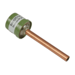
Hydro-Pro - High Pressure Switch 3.2 MPa / 4.4 MPa (Green) for Type P Heat Pump - 7011008
27,95 €

Hydro-Pro - PC 1001 Electronic Controller for Type P On/Off Heat Pump (P/32 Series) - 7027823
142,95 €

Hydro-Pro - PC 1001 Electronic Controller for Type P Series Heat Pump (P6/32) - 7026538
180,45 €

Flotide/MEGA - Heat Pump Water Flow Switch with 32 mm Glue Adapter - 7006471
51,45 €

Hydro-Pro - 2-Way Wire Connector, White, 450 V / 4 mm² - 7011019
4,95 €

Hydro-Pro - Built-In Refrigerant Pressure Gauge 0–65 bar (R32) - 7024868
52,45 €

Hydro-Pro - 10-Metre Extension Cable with Controller Housing for Type P On/Off Heat Pump (White) - 7025168
52,45 €

Descripción
Hydro-Pro Heat Pump Type P On/Off (Type P8/32) exploded view & spare parts
This page provides the full exploded-view diagram and numbered bill of materials (BOM) for the Hydro-Pro Heat Pump, Type P On/Off, model reference P8/32, sold under factory reference 7024525. The P8/32 is a horizontal, on/off pool heat pump rated at approximately 8.3 kW heating capacity, designed for pools up to 30–40 m³ and operable down to –5 °C using R32 refrigerant. The diagram covers every major assembly — from the refrigerant circuit and electrical box through to the fan section and water connections — so you have a complete picture of how the unit is constructed. Whether you are a pool owner carrying out routine maintenance or a technician diagnosing a fault, the diagram and parts list below will help you identify the exact component you need in minutes.
Cómo utilizar el esquema numerado para localizar tu pieza
Every numbered call-out on the exploded diagram corresponds directly to a row in the parts table beneath it: locate the area of the unit where your part lives, note the position number printed beside it, then find that same number in the BOM to retrieve the description and SKU. Once you have the SKU, simply enter it into the search bar or add the item straight to your basket. Bear in mind that some position numbers appear in more than one location on the drawing — this is common for items such as wire connectors (positions 1 and 30) that are used in multiple places inside the electrical box; always read the description column to confirm you have the right variant. Pay close attention to lettered suffixes: position 27 splits into 27a y 27b, which are two distinct controller boards — selecting the wrong letter will result in an incompatible part being delivered. Where a position row carries no SKU, the component is a structural or refrigerant-circuit part that is not offered separately as a service part; if you believe one of these items has failed, please contact our team for guidance before ordering. Finally, note that position 33 is a compound row covering several accessories listed together — read the full description carefully to identify the individual item you require and its corresponding SKU.
Main replaceable assemblies on the Hydro-Pro Type P8/32
The P8/32 is built around four broad functional groups, all of which are represented in the numbered diagram. The refrigerant circuit centres on the compressor (pos. 8, model WHP06760GUV-C8LU), the titanium heat exchanger (pos. 3, SKU 7024874), the 4-way reverse valve (pos. 21) that enables both heating and cooling modes, the low-pressure switch at 0.3/0.15 MPa (pos. 20, SKU 7011009), and the high-pressure switch at 3.2/4.4 MPa (pos. 24, SKU 7011008) — the two pressure switches are among the most commonly replaced safety components on this unit. The fan section comprises the axial fan motor 35 W YDK35-6 (pos. 14, SKU 7024869), the four-blade 440 mm fan blade with its 10 mm anticlockwise-rotation hub (pos. 13, SKU 7011024), the fan motor bracket (pos. 12), and the fan motor net guard (pos. 11). The electrical and controls group includes the PC 1001 controller board (pos. 27a/27b — see variant guidance below), the LCD touch-screen display assembly with Wi-Fi (pos. 10, SKU 7016596), the relay (pos. 29), the 60 µF round capacitor (pos. 2, SKU 7010433) which serves the compressor, and the 3 µF square plug-in capacitor (pos. 4, SKU 7010417) which serves the fan motor. The water-side components include the titanium heat exchanger already noted, the water flow switch with 32 mm glue adapter (pos. 28, SKU 7006471) — a frequent service item because it governs automatic start/stop — and the Hydro-Pro+ needle valve (pos. 19, SKU 7006466). The top lid measuring 956 × 360 mm (pos. 18, SKU 7033047) is the primary weather-protection cover and is available as a standalone replacement should it be cracked or lost.
Choosing between variants and pack sizes
The most important variant decision on this diagram is between position 27a (SKU 7027823, PC 1001 controller board suffix P8/32) and position 27b (SKU 7026538, the standard PC 1001 controller board without that suffix). The two boards carry the same base controller reference (82300022-35005-310457) but are calibrated differently; fitting the wrong version may cause incorrect temperature readings or prevent the unit from operating correctly, so always cross-reference your existing board’s label before ordering. For wire connectors, note that position 1 (5-way connector, SKU 7011025) and position 30 (2-way connector, SKU 7011019) are distinct items despite appearing similar — count the wire terminals on your existing connector before selecting. The fan blade at position 13 is specified as anticlockwise rotation with a 10 mm centre hole and a 440 mm tip-to-tip diameter; substituting a blade with a different rotation direction or hole size will either reduce airflow significantly or prevent fitment altogether. Where accessories such as the pressure meter, temperature sensors, rubber feet, and union couplers are grouped together under position 33, check each item’s individual SKU (listed within that row’s description) to ensure you are ordering only the specific piece you need.
