


Hydro-Pro Heat Pump, Type P On/Off (Type P14/32) exploded view & spare parts
 Certificado tienda en línea
 Devoluciones fáciles dentro de 14 días


Lista de piezas de repuesto

Hydro-Pro - Titanium Heat Exchanger for Type P14/32 Heat Pump - 7024876
586,45 €
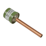
Hydro-Pro - High Pressure Switch 3.2 MPa / 4.4 MPa (Green) for Type P Heat Pump - 7011008
27,95 €

Hydro-Pro - Heat Pump Low Pressure Switch 0.3 MPa / 0.15 MPa - 7011009
27,95 €

Hydro-Pro - Brass High-Pressure Needle Valve 20000-140150 - 7006466
9,45 €

Hydro-Pro - LCD Touch-Screen Display Assembly with Wi-Fi (Type P On/Off) - 7016596
217,95 €

Hydro-Pro - Replacement Fan Blade 500mm × 145mm, 10mm Bore, Anticlockwise (Set of 4) - 7024880
59,95 €

Hydro-Pro - Axial Fan Motor 80W YDK80-6 - 7024872
202,95 €
Hydro-Pro - Heat Pump Top Lid 1115 x 430 mm (Type P On/Off) - 7033048
120,45 €

Motor Run Capacitor 60µF Round AMP - 7010433
39,95 €

Flotide/MEGA - Heat Pump Water Flow Switch with 32 mm Glue Adapter - 7006471
51,45 €

Hydro-Pro - 2-Way Wire Connector, White, 450 V / 4 mm² - 7011019
4,95 €

Hydro-Pro - Heat Pump PC 1001 Wire Controller for Type P Series (P14/32) - 7027825
142,95 €

Hydro-Pro - PC 1001 Electronic Controller for Type P Series Heat Pump (P6/32) - 7026538
180,45 €

Hydro-Pro - Condensador de marcha del motor del ventilador de 5 µF (redondo, con cables) – Bomba de calor tipo P, encendido/apagado (P14/32) - 7010418
26,45 €

Hydro-Pro - Built-In Refrigerant Pressure Gauge 0–65 bar (R32) - 7024868
52,45 €

Hydro-Pro - 10-Metre Extension Cable with Controller Housing for Type P On/Off Heat Pump (White) - 7025168
52,45 €

Descripción
Hydro-Pro Heat Pump, Type P On/Off (Type P14/32) exploded view & spare parts
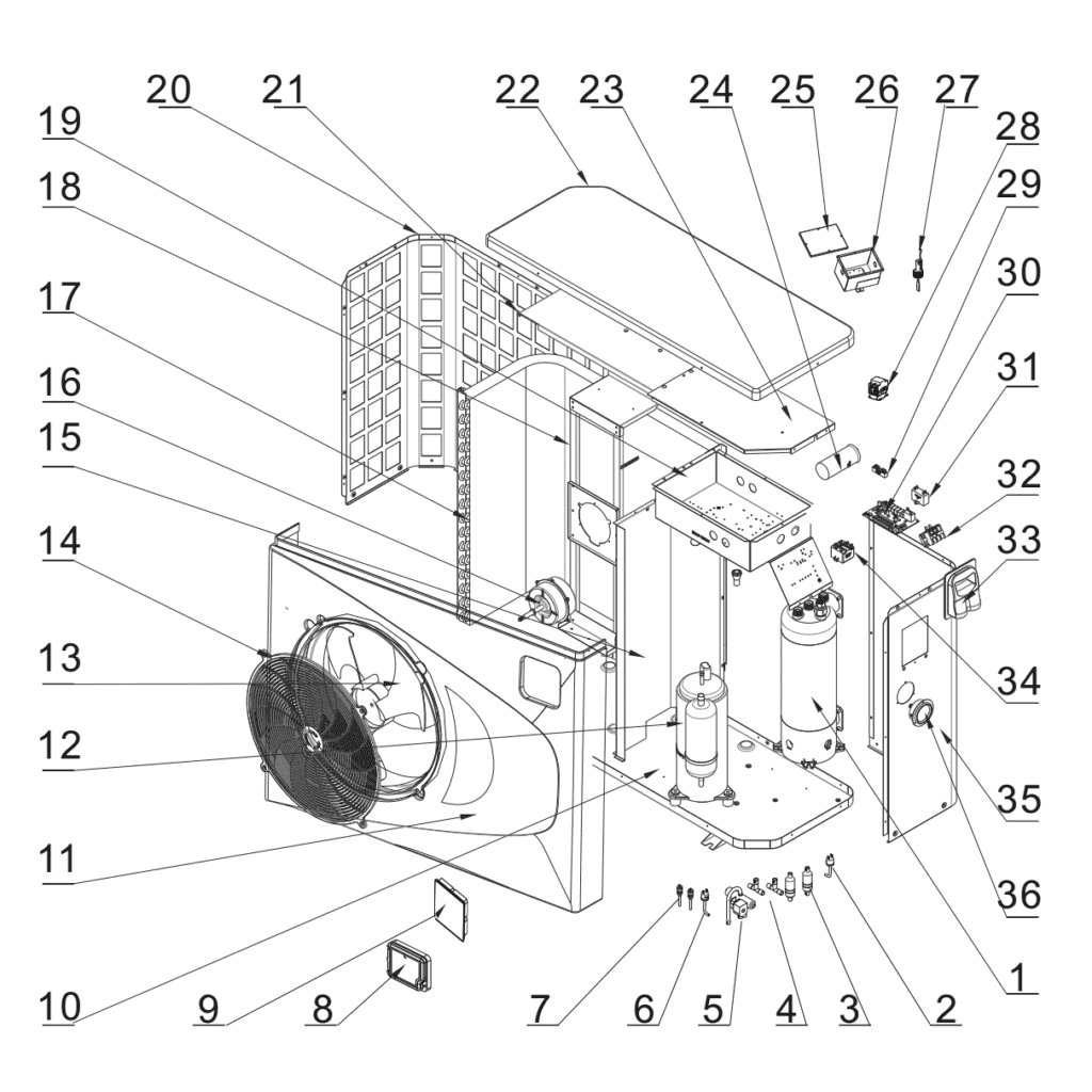
This page provides the official exploded-view diagram and full bill of materials for the Hydro-Pro Heat Pump, Type P On/Off, model P14/32, carried under factory reference 7024527. The P14/32 is a single-phase, on/off pool heat pump rated at 13.5 kW heating capacity (at A27/W27 conditions), designed for in-ground and above-ground pools and suited to pool volumes of approximately 50–68 m³. The diagram covers every major assembly — from the refrigerant circuit and electrical box through to the enclosure panels and water-side components. Work through the numbered call-outs below and you will be able to pinpoint the exact part you need within minutes.
Cómo utilizar el esquema numerado para localizar tu pieza
Every call-out number printed on the exploded-view diagram corresponds directly to a numbered row in the parts list table below the diagram. The most efficient way to find your part is to start by identifying the area of the unit that concerns you — for example, the refrigerant circuit, the electrical box, or the fan assembly — then locate the relevant call-out number in that zone of the drawing. Once you have the number, find the matching row in the table to confirm the description and, where stocked, the SKU you need to add to your basket. Bear in mind that a single position number can appear in more than one location on the drawing: common fasteners and fittings are sometimes shared across several sub-assemblies, so always read the part description carefully to be sure it matches what you see on your unit. Pay particular attention to lettered variants — position 30 in this diagram splits into 30a y 30b, which are two distinct controller part numbers for different unit configurations; ordering the wrong letter variant will result in an incompatible board. Parts shown in the diagram without a SKU in the table are either structural panels or refrigerant-circuit components that are not supplied as individual service parts; if you need one of those items, please contact us before ordering. Finally, note that some rows in the BOM bundle accessories or sensors alongside the primary part — read the full description text, not just the position number, to make sure you are selecting the correct item.
Main replaceable assemblies on the Hydro-Pro Type P On/Off (P14/32)
The refrigerant circuit forms the core of the unit and contains the components most likely to require service attention. Position 1 is the titanium heat exchanger (SKU 7024876), which transfers heat from the refrigerant to the pool water; titanium construction makes it resistant to chlorinated and salt-treated water. The high-pressure switch at position 2 (SKU 7011008, rated 3.2 MPa / 4.4 MPa) and the low-pressure switch at position 6 (SKU 7011009, rated 0.3 MPa / 0.15 MPa) are the two pressure-safety devices that protect the refrigerant circuit; both are individually stocked and straightforward to replace. Position 5 is the 4-way reverse valve, which governs the direction of refrigerant flow and enables the heat-pump cycle. The compressor at position 12 (model LV32VTAMC) is the heart of the refrigerant loop; this is not currently stocked as a standalone spare, so contact us if compressor replacement is required. On the air side, position 16 is the axial fan motor (80 W, YDK80-6, SKU 7024872), and position 13 is the matched 500 mm × 145 mm, 10 mm bore anticlockwise fan blade (SKU 7024880) — these two are closely related and should be verified together when diagnosing air-flow faults. Position 27 is the water flow switch with 32 mm glue adapter (SKU 7006471), which prevents the unit running without adequate water flow. The electrical box (position 19) houses several individually serviceable components: the PC 1001 controller boards at position 30a/30b, the 60 µF round AMP capacitor at position 24 (SKU 7010433), the 5 µF square plug-in capacitor at position 31 (SKU 7010418), the 2-way wire connector at position 29 (SKU 7011019), and the 5-way wire connector at position 32 (SKU 7011025). The user interface is the LCD touch-screen display assembly with Wi-Fi at position 8 (SKU 7016596), which mounts on the front of the cabinet. Position 7 is the Hydro-Pro+ Premium needle valve (brass, SKU 7006466), fitted within the refrigerant circuit, and position 22 is the top lid (1115 × 430 mm, SKU 7033048), which can be replaced if the enclosure is damaged.
Choosing between variants and pack sizes
The most important variant decision on this diagram is at position 30, where the controller splits into two distinct options: 30a (SKU 7027825) is the PC 1001 controller specified specifically for the P14/32 unit, while 30b (SKU 7026538) is the same controller board in a non-P14/32 configuration — the factory references printed on the two boards differ, and fitting the wrong variant can result in incorrect sensor calibration or control behaviour, so confirm your unit’s factory reference (7024527 for the P14/32) before ordering. Similarly, the two pressure switches at positions 2 y 6 carry different trip-point ratings (3.2 MPa / 4.4 MPa for the high-pressure switch versus 0.3 MPa / 0.15 MPa for the low-pressure switch) and are not interchangeable despite looking similar in the diagram — always match the SKU to the position number. The two capacitors at positions 24 y 31 also differ in capacitance, physical format, and connector type (60 µF round AMP versus 5 µF square plugged), so verify both the µF rating and the connector style against the label on the original component before purchasing a replacement.
