


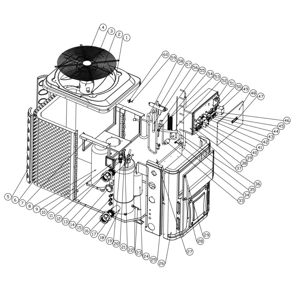
Bomba de calor Hydro-Pro (tipo 26T): vista explosionada y piezas de recambio
 Certificado tienda en línea
 Devoluciones fáciles dentro de 14 días


Lista de piezas de repuesto

Hydro-Pro - Panel de control LED de encendido/apagado para bomba de calor XK 001 V1 MM011 - 7010515
168,45 €

Hydro-Pro - Panel de control LED con conexión WiFi para encendido/apagado de bombas de calor (tipo WiFi12iMM011) - 7023601
302,95 €
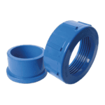
Hydro-Pro - Juego de conexión de agua con racor de encolado de 50 mm (paquete de 2) - 7014127
41,95 €

Manómetro 0–55 bar R410A - 7010518
47,45 €
Hydro-Pro - Juego de conexión de agua con racor de encolado de 50 mm (paquete de 2) - 7014127
41,95 €

Hydro-Pro - Intercambiador de calor de titanio para bomba de calor tipo 26 / 26T (ABS) - 7020789
1.051,45 €

Flotide/MEGA - Interruptor de caudal de agua para bomba de calor con adaptador para encolar de 32 mm - 7006471
51,45 €
Flotide/MEGA - Sensor de temperatura de salida de agua T2 - 7010535
10,45 €

Sensor de temperatura de entrada de agua T1 para la bomba de calor Hydro-Pro - 7010534
10,45 €
Sensor de temperatura para tuberías T3 - 7010533
12,45 €
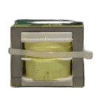
Hydro-Pro - Placa de circuito impreso de recambio ZK 102 V1 para bomba de calor tipo 13 - 7010514
168,45 €

Flotide/MEGA - Transformador para bomba de calor ZHL-03/EL-48 - 7010532
26,45 €
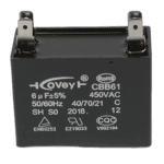
Hydro-Pro - Condensador para motor de ventilador de 6 µF, tipo cuadrado con conector enchufable - 7019180
9,95 €

Bloque de bornes para motor 380–400 V / 16 A - 7010526
6,45 €

Flotide/MEGA - Relé de secuencia de fases para bomba de calor tipo 12 - 7017965
103,45 €

Flotide/MEGA - Interruptor de baja presión 0,1–0,3 MPa (bomba de calor A3/32) - 7024791
21,95 €

Flotide/MEGA - Interruptor de alta presión para bombas de calor 3,6–4,2 MPa - 7024793
21,95 €
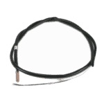
Sensor de temperatura ambiente para bomba de calor Hydro-Pro T5 - 7010537
10,45 €

Descripción
Bomba de calor Hydro-Pro (tipo 26T): vista explosionada y piezas de recambio
This page provides the official exploded-view diagram and full bill of materials for the Hydro-Pro Heat Pump Type 26T (factory reference 7018530), the largest model in the Hydro-Pro P-series range. The 26T is a three-phase unit, designed for larger pool installations. The Hydro-Pro P-series comes in black ABS casing, with a titanium heat exchanger that provides protection from chlorine, bromine, salt, and all natural outdoor elements. The diagram covers every major sub-assembly — from the control electronics and water circuit to the refrigerant circuit and enclosure panels — so you should be able to identify the numbered part you need within minutes.
Cómo utilizar el esquema numerado para localizar tu pieza
Every numbered call-out on the diagram corresponds directly to a row in the parts list below it; locate the area of the unit where your worn or damaged component sits, then find the matching position number in the diagram. Once you have the position number, look across the same row in the table to find the part description and, where stocked, the SKU you will enter at checkout. Bear in mind that some position numbers carry a letter suffix — positions 10a, 10b, and 10c denote three distinct display variants sharing the same physical mounting location, while positions 54a and 54b denote the low-pressure and high-pressure switches respectively; ordering the wrong lettered variant will result in an incompatible part. Where a position number appears in more than one location on the diagram (for example, rubber seals at positions 12 and 17, or water connection sets at positions 11 and 16), the diagram is calling out an identical or related part used in multiple spots — always count how many you require before adding to your basket. Some positions in the BOM do not yet carry a SKU; these are structural or refrigerant-circuit components not currently sold individually. If the SKU field for your position is blank, please use the contact form to enquire about availability before ordering a substitute.
Main replaceable assemblies on the Hydro-Pro Heat Pump (Type 26T)
The Type 26T divides naturally into four service areas. The control and display group centres on position 39 (PC Board ZK 101 V1, SKU 7010514), which governs all operating logic, together with the display panel at position 10a (LED display On/Off XK 001 V1 MM011, SKU 7010515) or the WiFi-enabled alternative at 10b (SKU 7023601). Supporting electronics in the electric box include the transformer at position 40 (SKU 7010532), the capacitor at position 41 (SKU 7019180), the terminal block at position 46 rated at 380–400 V / 16 A (SKU 7010526), and the phase sequence relay at position 51 (SKU 7017965), which is a critical protection component on this three-phase model. The circuito de agua runs through the titanium heat exchanger at position 18 (SKU 7020789), a titanium unit that resists corrosion from pool chemicals and is oversized to maximise thermal efficiency. Water enters and exits through the 50 mm glue-socket connection sets at positions 11 and 16 (both SKU 7014127), and flow is monitored by the water flow switch at position 19 (SKU 7006471) — an integrated switch that senses water movement and automatically starts the heat pump when the pool pump runs, and stops it when the pool pump shuts off. Pool water temperatures are tracked by three sensors: the water-in sensor T1 at position 23 (SKU 7010534), the water-out sensor T2 at position 21 (SKU 7010535), and the pipe sensor T3 at position 27 (SKU 7010533). Ambient conditions are read by sensor T5 at position 59 (SKU 7010537). The circuito de refrigerante includes the 4-way reversing valve (positions 56 and 57), the electronic expansion valve at position 34, and pressure protection via the low-pressure switch at position 54a (SKU 7024791) and the high-pressure switch at position 54b (SKU 7024793). Finally, the enclosure comprises the left side panel (25), front panel (26), maintenance covers (28 and 29), electric box cover (48), and the base tray (13), none of which are currently listed with individual SKUs.
Elegir entre variantes y tamaños de envase
Position 10 offers three distinct variants — 10a, 10b, and 10c — and it is essential to identify which display your unit was supplied with before ordering. Position 10a (SKU 7010515) is the standard wired LED panel (model reference XK 001 V1 MM011), while position 10b (SKU 7023601) is the WiFi-enabled model (WiFi02iMM101); the two are not interchangeable because they use different communication protocols with the PC board at position 39. Position 10c (the waterproof box) has no SKU and is therefore not available to order individually at this time. Similarly, positions 54a and 54b are both pressure switches but operate at entirely different pressure ranges — 0.1–0.3 MPa for the low-pressure switch (54a, SKU 7024791) and 3.6–4.2 MPa for the high-pressure switch (54b, SKU 7024793) — and fitting the wrong one will compromise the safety protection of the unit. Where the same SKU appears at two positions (such as SKU 7014127 at both position 11 and position 16), check the diagram carefully to establish how many pieces you need, as the connection set is used on both the inlet and outlet sides of the water circuit.
