



Norsup bomba de calor, inversor tipus Pv (tipus P35V/32), vista desmuntada i peces de recanvi
 Certificat botiga en línia
 Devolucions fàcils dins 14 dies


Llista de recanvis

Norsup - Fan Motor 250W ZWS250-A51 - 7027687
450,95 €
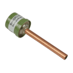
Hydro-Pro - Interruptor d'alta pressió 3,2 MPa / 4,4 MPa (verd) per a bomba de calor tipus P - 7011008
27,95 €

Hydro-Pro - Interruptor de baixa pressió per a bomba de calor 0,3 MPa / 0,15 MPa - 7011009
27,95 €

Flotide/MEGA - Interruptor de flux d'aigua per a bomba de calor amb adaptador d'encolatge de 32 mm - 7006471
51,45 €

Norsup - Intercanviador de calor per a bombes de calor inversores P35V/32 i P35TV/32 - 7027695
1.022,45 €

Norsup - Pala de ventilador d'alumini Ø600 mm × 150 mm, en sentit antihorari (forat de 12 mm) - 7027689
195,45 €

Hydro-Pro - Conector de cable de 2 posicions, blanc, 450 V / 4 mm² - 7011019
4,95 €

Norsup - PCB Controller PC1004 for Heat Pump Type P35V/32 - 7027676
255,45 €

Descripció
Norsup Heat Pump PV Inverter (Type P35V/32) exploded view & spare parts
This page provides the official exploded-view diagram and full bill of materials (BOM) for the Norsup Heat Pump PV Inverter, type P35V/32, carrying factory reference 7026973. The PV series sits within Norsup’s vertical-format full-inverter range, sharing the 35 kW output class and R32 refrigerant circuit found across the broader Norsup /32 inverter family, while using a vertical airflow configuration and a dedicated variable-speed inverter drive board. The diagram maps every component from the chassis and evaporator through to the control electronics and water-side connections, covering all 40 numbered positions in the BOM. Whether you are a pool technician performing a planned service or a pool owner investigating an unexpected fault, you should be able to identify the exact part you need within a few minutes using the numbered call-outs below.
Com utilitzar el diagrama numerat per trobar la teva peça
Start by locating the area of the heat pump where you believe the fault or wear lies — for example, the fan assembly at the top, the refrigerant circuit in the middle section, or the electrical box on the front panel. Each numbered call-out in the diagram corresponds directly to a single row in the parts list below it; finding the number on the drawing gives you the description and, where one has been assigned, the SKU you need to order. Note that some components appear physically in more than one location on the unit — positions 10 and 11, for instance, are both described as needle valves, and positions 25 and 26 are both conduit bends; always cross-reference the description column to confirm you have selected the correct one. Pay close attention to the wording of each description, as seemingly similar parts can differ in rated pressure, port size, or orientation. Position 41 is used differently from the rest: rather than a single part, it groups a collection of optional accessories and sensors — including temperature sensors, a pressure gauge, a Wi-Fi module, a display extension cable, a winter cover, and drain fittings — each carrying its own individual SKU listed within the description text. Where a position has no SKU shown, the part is not currently offered as a separate line item; if you need one of those structural components, contact us directly and we can advise on availability. Always verify the SKU description against the part on the unit before ordering, particularly for electronically controlled components.
Main replaceable assemblies on the Norsup Heat Pump PV Inverter (Type P35V/32)
The fan assembly at the top of the unit centres on position 1, the 250 W ZWS250-A51 fan motor (SKU 7027687), paired with the Φ600 mm × 150 mm fan blade at position 33 (SKU 7027689), which is specified as a 12 mm bore, anticlockwise-rotation blade — the correct rotation direction is critical for proper airflow through the evaporator. The evaporator coil itself sits at position 30, while the fan protection plate (position 5), fan net (position 34), and left and right protection nets (position 35) form the surrounding enclosure. The refrigerant circuit includes the high-pressure switch at position 6 (rated 3.2 MPa cut-out / 4.4 MPa reset, SKU 7011008), the low-pressure switch at position 7 (rated 0.3 MPa / 0.15 MPa, SKU 7011009), the electronic expansion valve at position 8, and the fluid reservoir at position 19, all of which are common service points on inverter heat pumps. The titanium heat exchanger at position 20 (SKU 7027695) is explicitly listed as covering both the P35V/32 and P35TV/32 models, making it a shared component across this sub-family. On the water side, position 12 carries the water flow switch with glued 32 mm adapter (SKU 7006471), which protects the heat exchanger by confirming water circulation before the compressor is permitted to run. The electrical and control section includes the PC1004 PCB controller at position 38 (factory reference 72200033-20000-430227, SKU 7027676), the inverter driver board at position 36 (reference ZGWTPHN6PY00-H, SKU 7027681), and the colourful display at position 15 (reference 20000-430176-8200047, SKU 7024942), all of which are specific to the PV inverter platform. The 2-way wire connector at position 37 (SKU 7011019) is a small but important electrical component that links sub-assemblies within the junction box. The compressor at position 22 (model SVB220FLGMC-L) and its bracket at position 21 form the heart of the refrigerant cycle, mounted on the chassis (position 24) with vibration isolation provided by the compressor bracket.
Tria entre variants i mides de paquet
The heat exchanger at position 20 is described as fitting both the P35V/32 and the P35TV/32, so if you own either variant within this 35 kW vertical sub-family you can order SKU 7027695 with confidence. The two needle valves — positions 10 i 11 — are distinguished in the BOM only by the labels (1) and (2); if you need to replace one, consult the diagram carefully to identify which of the two refrigerant-circuit service valves corresponds to the faulty position on your unit. For the fan blade at position 33, the specification is precise: Φ600 mm diameter, 150 mm pitch, 12 mm shaft hole, anticlockwise rotation — substituting a clockwise blade or an incorrect bore size will result in reversed airflow or mechanical failure, so do not approximate. The accessory group at position 41 lists items in a range of sizes and connection standards, such as the Flotide/MEGA union coupler in 50 mm × 1½” and the drain hose at a specific 102 cm length with 12 mm bore; always match the stated dimensions to your existing plumbing before ordering any accessory from this group.
