


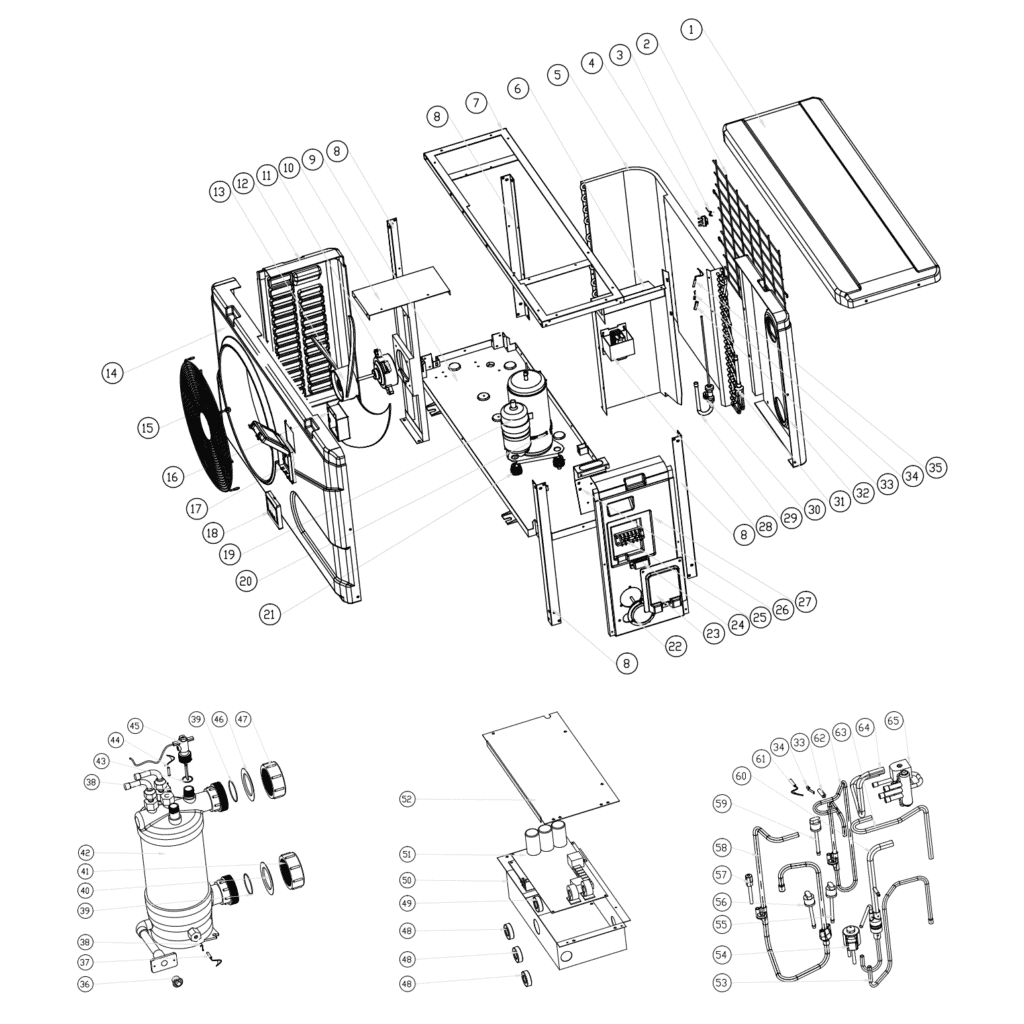
Norsup bomba de calor, tipus inversor (tipus Xp07Dcsi), vista desglossada i peces de recanvi
 Certificat botiga en línia
 Devolucions fàcils dins 14 dies


Llista de recanvis

Flotide/MEGA - Sensor de temperatura ambient TH1 amb connector de presa (6×4) - 7020259
15,95 €

Hydro-Pro - Motor de ventilador de bomba de calor WZD-25 25W - 7021811
310,45 €

Flotide/MEGA - Heat Pump Fan Blade 401mm × 119mm, 8mm Bore, Anticlockwise - 7021814
41,95 €

Flotide/MEGA - Caixa de visualització impermeable per a bomba de calor inversora (tipus Xp05Csie) - 7010543
31,45 €

Flotide/MEGA - Inversor de bomba de calor amb pantalla LED SHHCLEDV2MM101 - 7021826
226,95 €

Flotide/MEGA - Panell de visualització LED amb Wi-Fi per a bomba de calor inversora (WiFi02iMM011) - 7023600
252,45 €

Flotide/MEGA - Cinturó calefactor de carter de compressor 230V 35W 340mm - 7020267
44,45 €

Manòmetre 0–55 bar R410A - 7010518
47,45 €
Flotide/MEGA - Pipe Temperature Sensor TH2 with 6×4 Plug - 7020260
12,45 €

Flotide/MEGA - Tap de plàstic per a canonades PP amb rosca exterior ½" 10 bar negre - 0121241
3,45 €

Flotide/MEGA - Sensor de temperatura de l'aigua d'entrada TH6 amb endoll (6×4) - 7020263
15,95 €

Norsup - Titanium Heat Exchanger for Inverter 7 Heat Pump (XP07DCSI) - 7021827
643,45 €

Flotide/MEGA - Sensor de temperatura de sortida d'aigua TH5 amb endoll (6×4) - 7020262
15,95 €

Flotide/MEGA - Interruptor de flux d'aigua amb endoll VH-2 (9×7 mm) - 7020257
100,95 €

Flotide/MEGA - Placa de control d'inversor de bomba de calor SH0150101-V1.5 - 7021834
559,45 €
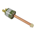
Interruptor de protecció de pressió alta 2,9/2,3 MPa (Verd) - 7010530
21,95 €

Flotide/MEGA - Sensor de temperatura d'escapament TH3 amb endoll (6×4) - 7020261
15,95 €

Descripció
Norsup Heat Pump, Type Inverter (Type XP07DCSI) exploded view & spare parts
This page covers the complete exploded-view diagram and bill of materials for the Norsup Heat Pump, Type Inverter, model designation XP07DCSI, supplied under factory reference 7021075. The diagram breaks the unit into every numbered component — from the outer cabinet panels and fan assembly right through to the refrigerant circuit and electronic controls — so you can pinpoint exactly what has failed or worn. The Norsup inverter range is built around full inverter technology, which modulates compressor speed to match heating demand. Key internal components, including the titanium heat exchanger, are chosen for durability and reliability. With 65 numbered positions covered in the diagram, most visitors find their part within a few minutes of landing on this page.
Com utilitzar el diagrama numerat per trobar la teva peça
Every numbered call-out printed on the exploded-view diagram corresponds directly to a numbered row in the parts list below it — locate the area of the unit that concerns you (cabinet, fan, refrigerant circuit, water circuit, or electronics), then read off the position number next to the component. Take that number, find the matching row in the BOM table, and note the SKU shown in the right-hand column — that SKU is the code you need to add to your basket. Bear in mind that not every position carries a purchasable SKU: some structural parts (panels, frames, pipework) are not offered as individual service items and will show no SKU against them. Where a position number appears more than once in the diagram — for example clips at positions 24 and 34, or low-pressure switches at positions 55 and 56 — each occurrence represents a distinct installation point, so count how many you need before ordering. Pay particular attention to lettered suffix variants: position 18a and position 18b are both LED display units but are different products with different SKUs, and fitting the wrong one will leave your control system non-functional. Always cross-reference the full description in the BOM (including wattage, dimensions, connector type, or part codes where shown) against what you remove from the machine before confirming your selection. If you are unsure, the SKU and description together give you everything our team needs to verify compatibility — use the on-page chat or contact form to ask.
Main replaceable assemblies on the Norsup Heat Pump Type Inverter (XP07DCSI)
The cabinet group forms the outer envelope of the unit and comprises the top cover (pos. 1), back grill (pos. 2), front panel (pos. 14), front grill (pos. 15), left side panel (pos. 12), right panel (pos. 27), back panel (pos. 32), and the structural top frame (pos. 7) and pillars (pos. 8) — these parts protect the internal components but are generally not stocked as individual spares. The fan assembly is a common service area: the fan motor (pos. 11, SKU 7021811) is a WZD-25 25 W unit, and the fan blade (pos. 13, SKU 7021814) is sized at 401 mm × 119 mm with an 8 mm anticlockwise-rotation hub, so both the motor and blade must be matched carefully. The full inverter design varies heating capacity to suit weather conditions, with a low-noise variable-speed fan motor that reduces both ambient noise and energy consumption. The refrigerant circuit centres on the compressor (pos. 19), which sits on damping feet (pos. 21) and is protected in cold weather by a 230 V 35 W heating belt (pos. 20, SKU 7020267); the four-way valve (pos. 65) and its associated pipework (pos. 63, 64) govern the heating and cooling mode changeover. Refrigerant-side safety is provided by the high-pressure protection switch (pos. 59, SKU 7010530, rated 2.9–2.3 MPa) and two low-pressure switches (pos. 55 and 56), along with the electronic expansion valve (pos. 54) and its connecting pipework. The water circuit runs through the titanium heat exchanger (pos. 42, SKU 7021827), with water temperature monitored by three sensors: water-in sensor TH6 (pos. 37, SKU 7020263), water-out sensor TH5 (pos. 44, SKU 7020262), and the water flow switch VH-2 (pos. 45, SKU 7020257) which protects the unit against dry running. The refrigerant side is further monitored by the ambient temperature sensor TH1 (pos. 3, SKU 7020259), the pipe temperature sensor TH2 (pos. 35, SKU 7020260), and the exhaust temperature sensor TH3 (pos. 61, SKU 7020261). The electronics bay houses the main PC board SH0150101-V1.5 (pos. 51, SKU 7021834) inside the electric box (pos. 50), the waterproof display box (pos. 17, SKU 7010543), and one of two LED display variants (pos. 18a/18b — see below). A pressure gauge (pos. 22, SKU 7010518) is fitted to the refrigerant circuit and is a useful diagnostic aid for service technicians.
Tria entre variants i mides de paquet
The most important variant choice on this unit is the LED display at position 18: the two options — 18a (SKU 7021826, module code SHHCLEDV2MM101) and 18b (SKU 7023600, module code WiFi02iMM011) — are not interchangeable. Position 18b is the Wi-Fi-enabled display, while 18a is the standard version; the Wi-Fi module allows you to control the heat pump with an app on your phone or tablet, so confirm which version is fitted to your unit before ordering. The three temperature sensors at positions 3, 35, 37, and 44 all share the same plug format (6×4) but carry different part numbers because each is calibrated or wired for a specific measurement point — ambient air, pipe, water-in, and water-out — so do not substitute one for another even if they look identical. The water connection sets at positions 41 and 47 share the same SKU (7014153), confirming they are identical items used at the inlet and outlet respectively, meaning a single order of two covers both sides of the heat exchanger. When ordering sealing rings (positions 39, 40, 43, 46), note that the BOM distinguishes between O-type sealing rings, blue rubber rings, and red rubber rings at specific locations in the water circuit — replacing like-for-like in terms of material and colour is important for correct sealing pressure and chemical compatibility.
