



Bomba de calor Hydro-Pro, tipus Z, inversor (tipus Z24/32), vista desmuntada i peces de recanvi
 Certificat botiga en línia
 Devolucions fàcils dins 14 dies


Llista de recanvis

Hydro-Pro - Cinturó de calefacció per a evaporador 230V 65W 2000mm - 7020274
58,95 €

Hydro-Pro - Motor de ventilador de bomba de calor ZWB378D02B 120W - 7021812
414,45 €

Hydro-Pro - Pala de ventilador per a bomba de calor inversora 496 mm × 150 mm, orifici de 12 mm, antihorari - 7021815
80,95 €

Flotide/MEGA - Inversor de bomba de calor amb pantalla LED SHHCLEDV2MM101 - 7021826
226,95 €
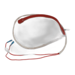
Hydro-Pro - Cinturó de calefacció del carter del compressor 230V 35W 430mm - 7025155
47,95 €

Flotide/MEGA - Manòmetre de pressió de refrigerant 63 mm 0–65 bar R32 connexió posterior 1/4" - 7025310
46,45 €

Flotide/MEGA - Interruptor de baixa pressió 0,1–0,3 MPa (Bomba de calor A3/32) - 7024791
21,95 €

Flotide/MEGA - Interruptor d'alta pressió per a bomba de calor 3,6–4,2 MPa - 7024793
21,95 €

Flotide/MEGA - Sensor de temperatura d'escapament TH3 amb endoll (6×4) - 7020261
15,95 €

Flotide/MEGA - Interruptor de flux d'aigua amb endoll VH-2 (9×7 mm) - 7020257
100,95 €

Flotide/MEGA - Sensor de temperatura de sortida d'aigua TH5 amb endoll (6×4) - 7020262
15,95 €

Hydro-Pro - Intercanviador de calor de titani per a bomba de calor inversora tipus Z (Z24/32) - 7025166
756,95 €
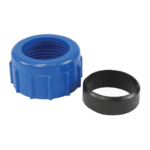
Connexió d'aigua de rosca compressió 50 mm - 7014126
41,95 €

Flotide/MEGA - Sensor de temperatura de l'aigua d'entrada TH6 amb endoll (6×4) - 7020263
15,95 €

Flotide/MEGA - Tap de plàstic per a canonades PP amb rosca exterior ½" 10 bar negre - 0121241
3,45 €

Hydro-Pro - Taula de control principal HWM1W-5D00 IB030R3A (inversor tipus Z Z19/32 i Z24/32) - 7025158
857,95 €

Hydro-Pro - Placa de control principal de bomba de calor FXB1-2 (inversor tipus Z24/32) - 7025311
41,95 €

Descripció
Bomba de calor Hydro-Pro, tipus Z, inversor (tipus Z24/32), vista desmuntada i peces de recanvi
This page provides the full exploded-view diagram and bill of materials (BOM) for the Hydro-Pro Heat Pump, Type Z Inverter — model designation Z24/32, catalogued under factory reference 7024520. The Z24/32 is a 25.5 kW inverter swimming pool heat pump that forms part of Hydro-Pro’s Type Z horizontal inverter range. The Type Z Inverter series is built around R32 refrigerant and an inverter-driven compressor and fan, making it one of the more technologically advanced options in the Hydro-Pro line-up. The diagram covers every numbered component from position 10 (isolation panel) through to position 75 (electric box), giving you a single reference point to identify and order the correct spare part in a matter of minutes.
Com utilitzar el diagrama numerat per trobar la teva peça
Every call-out number printed on the exploded-view diagram corresponds directly to a row in the parts list below, so start by locating the area of the unit where the fault or wear is visible — for example, the refrigerant circuit, the electrical box, or the water-side connections. Once you have identified the suspect area, find the matching position number on the diagram. Cross-reference that number with the BOM row to read the full part description and, where one is available, the SKU you will need to add to your basket. Bear in mind that some position numbers appear in more than one location on the diagram: a clip (positions 15 and 39, for instance) or a rubber sealing component may be used in several places across the unit, so always verify the description matches the specific location you are working on. Pay particular attention to lettered variants — position 26a and 26b, for example, both occupy the same mounting point on the front panel but are entirely different display assemblies, so you must confirm which variant is fitted to your unit before ordering. If a position number has no SKU listed, the component is not currently available as a standalone spare; contact us directly and we will advise on the best course of action. Working methodically through area → number → description → SKU will keep ordering errors to a minimum.
Main replaceable assemblies on the Hydro-Pro Heat Pump, Type Z Inverter (Type Z24/32)
El air-side section centres on the fan motor and blade assembly. Position 18 is the DC fan motor (ZWB378D02B, 120 W, SKU 7021812) and position 19 is the dedicated fan blade (496 mm × 150 mm, 12 mm bore, anticlockwise rotation, SKU 7021815); both are serviceable parts and should be replaced as matched components where possible. The circuit de refrigerant is the heart of the heat pump: the inverter compressor (pos. 29, MVB33FBPMC) works alongside the 4-way reversing valve (pos. 51), the electronic expansion valve (pos. 57), and the liquid reservoir (pos. 31). Safety monitoring on the refrigerant side is handled by the low-pressure switch at position 47 (0.1–0.3 MPa, SKU 7024791) and the high-pressure switch at position 52 (3.6–4.2 MPa, SKU 7024793); the R32 pressure gauge at position 38 (0–65 bar, SKU 7025310) allows on-site checking without disconnecting the circuit. The circuit vora l'aigua includes the titanium heat exchanger specific to this model size (pos. 63, SKU 7025166), the water flow switch (pos. 60, SKU 7020257), and three temperature sensors — water-out sensor TH5 (pos. 61, SKU 7020262), water-in sensor TH6 (pos. 67, SKU 7020263), and exhaust temperature sensor TH3 (pos. 53, SKU 7020261). The electrical section houses the main inverter control board HWM1W-5D00 IB030R3A (pos. 71, SKU 7025158), the secondary main board FXB1-2 (pos. 73, SKU 7025311), and the user-facing display (pos. 26a/26b). Winter protection is provided by two heating belts: the evaporator heating belt (pos. 16, 230 V / 65 W / 2000 mm, SKU 7020274) and the compressor heating belt (pos. 32, 230 V / 35 W / 430 mm, SKU 7025155).
Tria entre variants i mides de paquet
La elecció de la variant més important en aquest diagrama és a posició 26, the user display. Position 26a (SKU 7021826) is the LED display board (SHHCLEDV2MM101), while position 26b (SKU 7025263) is the colour TFT display (TSiV1) available on later Z-series units. These two boards use different connectors and firmware, so fitting the wrong variant will prevent the controller from communicating correctly; always check the label on your existing display or the serial-number sticker on the unit before ordering. For the water-connection components at positions 65 (blue rubber ring) and 69 (red rubber ring), note that colour coding indicates the water-flow direction — inlet and outlet — so order both rings together if you are dismantling the water connections to avoid accidental cross-fitting. The water connection set at position 64 (SKU 7014126) is specified as a 50 mm compression-type fitting compatible with ECO and Flotide/MEGA manifolds; confirm your pipework diameter and union style before purchasing, as an incorrect fitting size will either leak or require additional adapters. Where a component carries no SKU in the list, it means that part is not yet sold individually through this catalogue — in such cases, please use the contact details on this page and our team will advise whether a service replacement is available.
