



Pompa de căldură Norsup, tip Pv cu invertor (tip P21Tv/32) – vedere explodată și piese de schimb
 Certificat magazin online
 Retururi ușoare în termen de 14 zile


Lista pieselor de schimb

Norsup - Motor de ventilator 200 W ZWS200-B3 - 7027686
368,45 €
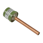
Hydro-Pro - Comutator de presiune înaltă 3,2 MPa / 4,4 MPa (verde) pentru pompa de căldură de tip P - 7011008
27,95 €

Hydro-Pro - Comutator de joasă presiune pentru pompă de căldură 0,3 MPa / 0,15 MPa - 7011009
27,95 €

Flotide/MEGA - Comutator de debit pentru apă pentru pompe de căldură cu adaptor de lipit de 32 mm - 7006471
51,45 €

Norsup – Schimbător de căldură din titan pentru pompele de căldură P21V/32 și P21TV/32 – 7027692
462,45 €

Norsup - Paletă de ventilator din aluminiu Ø560 mm × 150 mm, rotire în sens invers acelor de ceasornic (gaură de 12,7 mm) - 7027688
157,95 €

Norsup – Modul de control al vitezei ventilatorului 20000-430228 + 35005-310617 – 7027685
195,45 €

Norsup - Inverter Driver Board 2AC32I07WM1 for PV Heat Pump P21TV/32 - 7027680
1.191,45 €

Hydro-Pro - Conector cu 2 căi, alb, 450 V / 4 mm² - 7011019
4,95 €

Descriere
Norsup Heat Pump PV Inverter (Type P21TV/32) exploded view & spare parts
This page provides the official exploded-view diagram and full bill of materials for the Norsup Heat Pump PV Inverter, model type P21TV/32, listed under factory reference 7026968. The diagram covers the complete unit — from the refrigerant circuit and electrical box through to the casing panels and water connections — giving you a clear, numbered map of every serviceable component. It also covers the closely related P21V/32 variant where parts are shared, most notably the titanium heat exchanger at position 19. Using this page, you should be able to identify the exact part you need in a matter of minutes, then proceed straight to the relevant SKU.
Cum să folosiți schema numerotată pentru a găsi piesa dorită
Every circled call-out number printed on the exploded-view diagram corresponds directly to a numbered row in the parts list below. Start by locating the area of the unit where your fault or wear has occurred — for example, the top fan assembly, the refrigerant circuit, the electrical box, or the water circuit — and then scan for the call-out number closest to the component you are inspecting. Once you have that number, find the matching row in the table and note the part number (SKU) shown alongside it. Bear in mind that some generic components, such as relays, appear at more than one position in the diagram: position 35 and position 41 are both listed as “Relay”, so always confirm the location on the diagram before ordering rather than relying on the description alone. Similarly, position 24 and position 25 are both described as “conduit bend” — they may be identical or may differ in size or angle, so cross-reference carefully with the diagram. Where a position has no SKU listed, that part is not currently sold individually; in that case, please contact us so we can advise on the correct course of action. Finally, note that position 48 groups together a range of optional accessories and sensors — these each carry their own separate part numbers and are listed individually within that row.
Main replaceable assemblies on the Norsup PV Inverter P21TV/32
The fan assembly at the top of the unit is formed by the 200 W fan motor (position 1, SKU 7027686), the fan blade at position 32 (Φ560 mm × 150 mm, 12.7 mm bore, anticlockwise rotation, SKU 7027688), the fan net at position 33, and the fan protection plate at position 5. These are high-cycle components and among the most commonly replaced on any inverter heat pump. The refrigerant circuit includes the compressor SVB220FLGMC-L at position 21, supported on its bracket at position 20, along with the electronic expansion valve (position 8), the filter (position 9), and two needle valves at positions 10 and 11 for service access. Refrigerant-circuit safety is handled by the high-pressure switch rated 3.2 MPa / 4.4 MPa at position 6 (SKU 7011008) and the low-pressure switch rated 0.3 MPa / 0.15 MPa at position 7 (SKU 7011009). The titanium heat exchanger at position 19 (SKU 7027692) is specified to suit both the P21V/32 and the P21TV/32, confirming shared refrigerant-to-water circuit components across these two models. Water flow is monitored by the flow switch with 32 mm glue adapter at position 12 (SKU 7006471), which will interrupt operation if flow falls below the minimum threshold. The electrical box houses the main PC1004 PCB controller specific to the P21TV/32 type at position 40 (SKU 7027671), the inverter driver board 2AC32I07WM1 at position 42 (SKU 7027680), the fan speed control module at position 39 (SKU 7027685), and the filter plate 1AC32I20WL2 at position 45 (SKU 7027683). The user-facing colourful display panel at position 15 (SKU 7024942) and the front panel at position 14 complete the control interface. Wiring within and between assemblies is served by the 5-way wire connector at position 38 (SKU 7011025) and the 2-way wire connector at position 47 (SKU 7011019).
Alegerea între variante și dimensiunile ambalajelor
This diagram covers two closely related models: the standard P21V/32 and the three-phase P21TV/32. The “T” in the model designation indicates the three-phase (400 V) version, which is reflected most critically in the electrical components — the PC1004 PCB controller at position 40 (SKU 7027671) is explicitly specified for the P21TV/32 type, so it is essential to verify your model designation before ordering any electrical board. Shared mechanical and refrigerant-circuit parts — such as the heat exchanger at position 19 — carry the same SKU across both variants, but always confirm against your unit’s data plate rather than assuming compatibility. The fan blade at position 32 carries precise dimensional data (Φ560 mm × 150 mm, 12.7 mm bore, anticlockwise) — even a small deviation in bore diameter or rotation direction will result in incorrect fitment or reduced airflow, so do not substitute with a visually similar blade. Where optional accessories such as the Wi-Fi module (SKU 7027389), temperature sensors, or the winter cover (SKU 7027697) are required, these are listed in the accessories section at position 48 and each carries its own individual SKU, allowing them to be ordered separately to suit your specific installation needs.
