



Norsup Heat Pump, Type Pv Inverter (Type P17V/32) exploded view & spare parts
 Certified online store
 Easy returns within 14 days


Spare parts list

Norsup - Fan Motor 200W ZWS200-B3 - 7027686
368,45 €
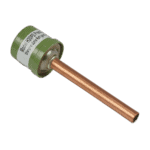
Hydro-Pro - High Pressure Switch 3.2 MPa / 4.4 MPa (Green) for Type P Heat Pump - 7011008
27,95 €

Hydro-Pro - Heat Pump Low Pressure Switch 0.3 MPa / 0.15 MPa - 7011009
27,95 €

Flotide/MEGA - Heat Pump Water Flow Switch with 32 mm Glue Adapter - 7006471
51,45 €

Norsup - Heat Exchanger for P17V/32 Inverter Heat Pump - 7027691
432,45 €

Norsup - Aluminium Fan Blade 522 mm × 140 mm, 3-Blade Anticlockwise - 7027709
150,45 €

Norsup - Fan Speed Control Module 20000-430228 + 35005-310617 - 7027685
195,45 €

Hydro-Pro - 2-Way Wire Connector, White, 450 V / 4 mm² - 7011019
4,95 €

Norsup - Inverter Driver Board 2AC81I01WM1 - 7027678
725,45 €

Descriere
Norsup Heat Pump, Type PV Inverter (Type P17V/32) — exploded view & spare parts
This page covers the complete exploded-view diagram and bill of materials for the Norsup Heat Pump PV Inverter, model designation Type P17V/32, listed under Norsup factory reference 7026966. The P17V/32 is a 230 V AC, vertical-discharge, full-inverter swimming pool heat pump rated at approximately 17 kW, designed for pools in the 45–80 m³ range. As a full inverter unit, it varies compressor and fan speeds continuously to match prevailing conditions, rather than simply switching on and off. The diagram breaks the unit down into 42 numbered positions spanning every major sub-assembly — from the refrigerant circuit through to the electrical enclosure — so you should be able to pinpoint the part you need within minutes.
How to use the numbered diagram to find your part
Every numbered call-out on the diagram corresponds directly to a row in the parts list below it: the position number in the diagram is the same number shown in the Pos. column of the table. The most efficient approach is to work spatially first — identify the area of the unit where the fault or wear has occurred (for example, the electrical enclosure, the refrigerant circuit, or the fan assembly), locate the relevant call-out number in that area of the diagram, then find that number in the parts list to retrieve the SKU. Bear in mind that some generic components — such as wire connectors (positions 35 and 38) — may appear at more than one location in the diagram because the same part is used several times within the unit; always cross-reference the description column to confirm the connector type (2-way or 5-way) before ordering. Position 42 in this diagram is an unusually composite entry: the inverter driver board is listed alongside a range of associated accessories and sensors under a single position number, so read the full description carefully and note the individual SKUs for each accessory if you need only one item from that group. Where a position number has no SKU shown, the item is a structural or sheet-metal component that is not currently available as a standalone spare; if you are uncertain whether a part can be ordered separately, contact us before purchasing. Always note the factory reference of the complete unit (7026966) when getting in touch, as this confirms you are working from the correct diagram revision.
Main replaceable assemblies on the Norsup P17V/32
The fan assembly at the top of the unit is made up of several discrete parts. The fan motor (position 1, SKU 7027686) is a 200 W ZWS200-B3 unit driving a 522 mm three-leaf anticlockwise fan blade (position 30, SKU 7027709); note that the blade is handed and sized precisely for this model, so substituting a generic blade is not advisable. Fan speed is governed by a dedicated fan speed control module at position 34 (SKU 7027685), which forms part of the variable-speed inverter circuit. The refrigerant circuit centres on the compressor (position 21, model SVB220FLGMC-L) mounted on its own bracket (position 20), with the evaporator (position 27) drawing ambient air through the rear and side protection nets (positions 28 and 32). Refrigerant pressures are monitored by the high-pressure switch at position 6 (SKU 7011008, rated 3.2 MPa/4.4 MPa) and the low-pressure switch at position 7 (SKU 7011009, rated 0.3 MPa/0.15 MPa); either switch may trigger a fault code if it fails or drifts out of calibration. Pool water passes through the titanium heat exchanger at position 19 (SKU 7027691, specific to the P17V/32), with flow confirmed by the water flow switch at position 12 (SKU 7006471), which is supplied with a 32 mm glue adapter. The entire refrigerant and water circuit is controlled by the PC1004 PCB controller at position 33 (SKU 7027669, factory reference 72200033-20000-430227), while the user interface is the colourful display at position 15 (SKU 7024942, factory reference 20000-430176-8200047) mounted on the front panel. The electrical enclosure also houses the filter plate at position 36 (SKU 7027682, reference AC19I32.RWL.150813) and the 2-way and 5-way wire connectors at positions 35 and 38 (SKUs 7011019 and 7011025 respectively), which are among the most commonly replaced electrical consumables on this platform.
Choosing between variants and pack sizes
Several positions in this bill of materials carry a qualifier in parentheses — for example, needle valve (1) at position 10 and needle valve (2) at position 11 — indicating that two physically distinct valves share a similar description but serve different points in the refrigerant circuit; always match the position number, not just the description. Position 42 lists the inverter driver board (SKU 7027678) alongside multiple accessories such as the Wi-Fi module (SKU 7027389), temperature sensors (SKUs 7011007 and 7024867), pressure gauge (SKU 7026259), and ancillary items, all under a single diagram call-out. Each of these accessories carries its own individual SKU and should be ordered separately unless you require the complete board and accessory bundle. The water connection accessories at position 25 and the fittings at position 24 have no individual SKUs in this revision of the diagram; if you need to replace those items, contact us with the unit’s factory reference (7026966) and a photograph so we can confirm the correct specification. For any threaded or push-fit components, always verify the nominal pipe diameter and connection standard before ordering — the water flow switch at position 12, for instance, is specifically sized for a 32 mm glue-socket fitting, and fitting a different size will compromise both the seal and the flow-detection accuracy.
