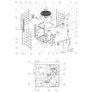
Norsup Heat Pump, Type Pv Inverter (Type P13V/32) exploded view & spare parts
 Certified online store
 Easy returns within 14 days


Spare parts list

Norsup - Fan Motor 200W ZWS200-B3 - 7027686
368,45 €
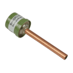
Hydro-Pro - High Pressure Switch 3.2 MPa / 4.4 MPa (Green) for Type P Heat Pump - 7011008
27,95 €

Hydro-Pro - Heat Pump Low Pressure Switch 0.3 MPa / 0.15 MPa - 7011009
27,95 €

Flotide/MEGA - Heat Pump Water Flow Switch with 32 mm Glue Adapter - 7006471
51,45 €

Norsup - Heat Exchanger for PV Inverter Heat Pump P13V/32 - 7027690
603,45 €

Norsup - Aluminium Fan Blade 522 mm × 140 mm, 3-Blade Anticlockwise - 7027709
150,45 €

Norsup - Fan Speed Control Module 20000-430228 + 35005-310617 - 7027685
195,45 €

Hydro-Pro - 2-Way Wire Connector, White, 450 V / 4 mm² - 7011019
4,95 €

Norsup - Inverter Driver Board 2AC81I01WM1 - 7027678
725,45 €

Descriere
Norsup Heat Pump Type PV Inverter (P13V/32) exploded view & spare parts
This page covers the complete exploded-view diagram and bill of materials for the Norsup Heat Pump Type PV Inverter, model P13V/32, sold under factory reference 7026965. The P13V/32 is a full-inverter, vertical-discharge swimming pool heat pump running on R32 refrigerant, designed to vary its heating output automatically to match ambient conditions. The diagram breaks the unit down into every major assembly and sub-component — from the refrigeration circuit and electrical box through to the fan stack and water connections — so you can locate and order the exact part you need. Work through the numbered call-outs below and you should be able to identify your part in a matter of minutes.
How to use the numbered diagram to find your part
Every circle or arrow in the exploded-view diagram carries a position number, and each of those numbers corresponds directly to a row in the parts list table on this page. Begin by identifying the area of the unit where your fault or wear is visible — for example, the fan stack at the top, the electrical box on the front, or the refrigeration circuit at the rear — then scan the diagram for the relevant call-out number in that zone. Once you have the number, find the matching row in the table; if a SKU appears in that row you can add it straight to your basket. Some components, such as structural panels, covers, and brackets, are listed for identification purposes but do not currently carry an individual SKU — these are shown in the table without a part number. Be aware that a single position number can sometimes refer to a fastener or fitting that appears in more than one location on the unit; always check the description carefully to confirm it matches your specific component. Position 42 in this diagram is particularly detailed: it groups the inverter driver board (SKU 7027678) together with a list of associated accessories and sensors — read the full description to establish which individual item within that assembly you require. Where a description includes bracketed variants — for example, position 10 “Needle valve (1)” and position 11 “Needle valve (2)” — these denote distinct components at different points in the refrigeration circuit, so confirm which needle valve location corresponds to your fault before ordering.
Main replaceable assemblies on the Norsup P13V/32
The fan stack at the top of the unit comprises the fan motor (position 1, SKU 7027686), the three-leaf fan blade (position 30, SKU 7027709), and the surrounding fan net (position 31) and fan protection plate (position 5). The fan blade is a 522 mm diameter, 140 mm pitch unit with a 12.7 mm bore and anticlockwise rotation — replacing like-for-like on these specifications is essential for correct airflow and motor loading. The refrigeration circuit runs from the compressor SVB220FLGMC-L (position 21) mounted on its bracket (position 20), through the electronic expansion valve (position 8), filter (position 9), and two needle valves (positions 10 and 11), to the high-pressure switch at 3.2/4.4 MPa (position 6, SKU 7011008) and the low-pressure switch at 0.3/0.15 MPa (position 7, SKU 7011009). The titanium heat exchanger specific to the P13V/32 sits at position 19 (SKU 7027690), supported by the titanium pipe support at position 18; this exchanger is the primary interface between the refrigerant and pool water circuits. The evaporator is listed at position 27. The water side is completed by the water flow switch with 32 mm glue adapter at position 12 (SKU 7006471) and the water connection and fittings at positions 24 and 25. The electrical enclosure houses the PC1004 PCB controller specific to the P13V/32 (position 33, SKU 7027668), the fan speed control module (position 34, SKU 7027685), the inverter driver board (position 42, SKU 7027678), the filter plate (position 36, SKU 7027682), relay (position 37), reactance (position 39), and wire connectors (positions 35 and 38). The user interface is the colourful display at position 15 (SKU 7024942), mounted behind the front panel (position 14) and secured by the surface box fixed plate (position 13).
Choosing between variants and pack sizes
The two needle valves on this unit — position 10 “Needle valve (1)” and position 11 “Needle valve (2)” — serve different points in the refrigeration circuit and are listed as separate line items; do not assume they are interchangeable without confirming their location in the diagram. Similarly, the two wire connectors differ by pin count: position 35 is the 2-way connector (SKU 7011019) and position 38 is the 5-way connector (SKU 7011025) — ordering the wrong one will result in a connector that cannot mate with its corresponding harness. The pressure switches at positions 6 and 7 are rated to specific cut-in and cut-out pressures (3.2/4.4 MPa and 0.3/0.15 MPa respectively); always verify these ratings against your unit’s data plate before fitting a replacement, as substituting a switch with different trip points can affect system safety and performance. For accessories associated with position 42 — such as the Wi-Fi module (7027389), extension cable and display housing (7025131), drain hose (7026961), and hosetail drain outlet (7026962) — each carries its own individual SKU and should be ordered separately rather than assuming they are included with the inverter driver board.