


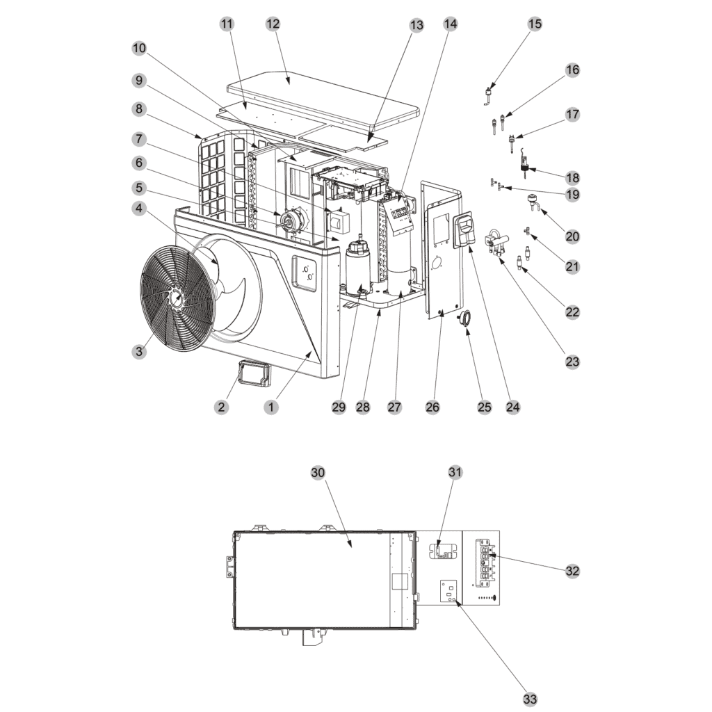
Hydro Pro Heat Pump Type PX30/32 exploded view & spare parts
 Certified online store
 Easy returns within 14 days


Spare parts list

Hydro-Pro - Black Glass Control Display CM404 - 7029494
285,45 €
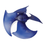
Hydro-Pro - Replacement Fan Blade 500mm × 145mm, 10mm Bore, Anticlockwise (Set of 4) - 7024880
59,95 €

Hydro-Pro - Axial Fan Motor 75W ZWS75-A - 7024943
315,45 €
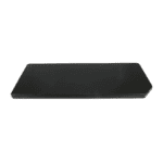
Hydro-Pro - Heat Pump Top Lid 1115 x 430 mm (Type P On/Off) - 7033048
120,45 €

Hydro-Pro - Heat Pump Low Pressure Switch 0.3 MPa / 0.15 MPa - 7011009
27,95 €
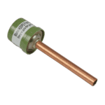
Hydro-Pro - High Pressure Switch 3.2 MPa / 4.4 MPa (Green) for Type P Heat Pump - 7011008
27,95 €

Flotide/MEGA - Heat Pump Water Flow Switch with 32 mm Glue Adapter - 7006471
51,45 €

Hydro-Pro - Panel-Mount Refrigerant Pressure Gauge 0–55 bar R32 - 7026259
44,95 €

Hydro-Pro - Titanium Heat Exchanger PIV 30/32 - 7025130
510,95 €

Hydro-Pro - Heat Pump Driver Board P20X/P26X M-Series - 7024940
1.093,95 €

Hydro-Pro - 2-Way Wire Connector, White, 450 V / 4 mm² - 7011019
4,95 €

Hydro-Pro - PC1004 PCB Controller for PIV 30/32 Heat Pump - 7029492
277,95 €

Hydro-Pro - Frequency Controller Board for P20X / P26X / P35X T-Series Heat Pumps - 7025126
398,45 €

Descriere
Hydro Pro Heat Pump Type PX30/32 exploded view & spare parts
This page provides the official exploded-view diagram and full bill of materials (BOM) for the Bosta Hydro Pro Heat Pump Type PX30/32 (factory reference 7028290). The PX30/32 is a 30 kW inverter-series pool heat pump suitable for heating pools up to 170 cubic metres of water. The Inverter range is designed for year-round use, featuring larger-than-standard heat exchangers and the latest rotary compressor design for effective heating performance even in the coldest months. The unit operates in ambient temperatures as low as −15 °C. Use the numbered diagram and the parts list below together to identify the exact component you need — most visitors locate their part within a few minutes.
How to use the numbered diagram to find your part
Every numbered call-out printed on the exploded-view diagram corresponds directly to a row in the parts table below — the position number in the diagram and the Pos. column in the table are always the same. Start by locating the general area of the unit where your suspect component sits — for example, the top fan section, the refrigerant circuit, or the electrical box — then read off the call-out number closest to that component. Once you have the position number, find the matching row in the table and note the SKU; that SKU is what you add to your basket. Bear in mind that some positions carry a bracketed suffix in their description, such as Filter (1) at position 22 and Filter (2) at position 23, or Electrical box (1) at position 13 and Electrical box (2) at position 39 — these are distinct parts even though they look similar on the diagram, so confirm which location you are working on before ordering. Position 17 is a further example of a busy call-out: it covers the high-pressure switch (SKU 7011008) and lists two temperature sensor variants (5K at SKU 7011007, and 50K at SKU 7024867) as related items — read that row carefully and select the variant that matches the sensor currently fitted to your unit. Not every position has a purchasable SKU; positions shown without a SKU are either service items or structural parts not sold separately, and these are indicated clearly in the table.
Main replaceable assemblies on the Hydro Pro Heat Pump Type PX30/32
The PX30/32 divides naturally into four working groups, each of which contains the parts most likely to need attention over the unit’s service life. The air-side assembly at the top of the cabinet comprises the fan blade (position 4 — a 500 mm × 145 mm anticlockwise blade with a 10 mm bore, SKU 7024880) driven by the 75 W axial fan motor ZWS75-A (position 5, SKU 7024943), protected externally by the fan protection net (position 3) and enclosed under the top lid measuring 1115 × 430 mm (position 11, SKU 7033048). The refrigerant circuit runs through the evaporator (position 8), the MVB42FCBMC-L compressor (position 29), the four-way reverse valve (position 25), the electronic expansion valve (position 20), and the fluid reservoir (position 30); the circuit operates on R32 refrigerant and its condition can be read on the pressure gauge rated 0–55 bar at position 24 (SKU 7026259). Safety within the refrigerant circuit is handled by the low-pressure switch rated 0.3 MPa / 0.15 MPa (position 15, SKU 7011009) and the high-pressure switch rated 3.2 MPa / 4.4 MPa (position 17, SKU 7011008). The water-side assembly centres on the titanium heat exchanger PIV 30/32 (position 27, SKU 7025130), which transfers heat to the pool water, with the water flow switch (position 18, SKU 7006471) protecting the unit against dry running. The electrical and control assembly, housed across two electrical boxes (positions 13 and 39) and the explosion-proof box (position 43), brings together the PC1004 PCB controller (position 37, SKU 7029492), the glass display CM404 (position 2, SKU 7029494), the driver board P20X/26X M-series (position 33, SKU 7024940), the frequency controller plate P20X/26X/35X T-series (position 40, SKU 7025126), the fan speed control plate P26X/35X series (position 45, SKU 7025129), and the two-seat connector (position 34, SKU 7011019).
Choosing between variants and pack sizes
Position 17 is the most important example of variant selection on this diagram: the high-pressure switch (SKU 7011008) is listed alongside two temperature sensor options — the 5K sensor (SKU 7011007) and the 50K sensor (SKU 7024867). These sensors are not interchangeable; fitting the wrong resistance value will cause incorrect temperature readings and may trigger nuisance fault codes, so check the markings on the sensor body or your service records before ordering. Position 4, the fan blade, is specified with precise dimensions (500 mm × 145 mm, 10 mm hole, anticlockwise rotation) — using a blade with a different pitch, diameter, or rotation direction will affect airflow across the evaporator and may overload the motor at position 5. Position 45 includes several accessory items described within a single BOM row — including a 10-metre extension cable and housing (SKU 7029497) and a winter cover (SKU 7025374) — each of which carries its own SKU; confirm you are selecting the specific accessory you require rather than the fan speed plate itself (SKU 7025129). Where the description references a thread size or connection standard, such as the 1/2" copper tube at position 16 or the 50 mm PVC union coupler referenced at position 45, always verify the fitting size against your pipework before purchasing to avoid mismatched connections.
