



Pompa de căldură Hydro-Pro, tip P On/Off (tip P6/32) – vedere explodată și piese de schimb
 Certificat magazin online
 Retururi ușoare în termen de 14 zile


Lista pieselor de schimb

Hydro-Pro - Manometru încorporat pentru agent frigorific 0–65 bar (R32) - 7024868
52,45 €

Hydro-Pro - Schimbător de căldură din titan pentru pompa de căldură P6/32 - 7024873
315,45 €
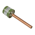
Hydro-Pro - Comutator de presiune înaltă 3,2 MPa / 4,4 MPa (verde) pentru pompa de căldură de tip P - 7011008
27,95 €

Hydro-Pro - Comutator de joasă presiune pentru pompă de căldură 0,3 MPa / 0,15 MPa - 7011009
27,95 €

Hydro-Pro - Supapă cu ac din alamă pentru presiune înaltă 20000-140150 - 7006466
9,45 €

Hydro-Pro - Ansamblu ecran LCD tactil cu Wi-Fi (tip P pornit/oprit) - 7016596
217,95 €

Hydro-Pro - Motor pentru ventilator axial 35 W YDK35-6 - 7024869
112,95 €

Hydro-Pro - Paletă pentru pompă de căldură 405 mm × 134 mm, cu 3 pale, rotire în sens invers acelor de ceasornic - 7024879
37,45 €

Hydro-Pro - Capac superior pentru pompă de căldură 746 × 289,5 mm (tip P, pornire/oprire) - 7033049
67,45 €

Hydro-Pro - Conector cu 2 căi, alb, 450 V / 4 mm² - 7011019
4,95 €

Hydro-Pro - Controler electronic PC 1001 pentru pompa de căldură din seria P (P6/32) - 7026538
180,45 €

Flotide/MEGA - Condensator de pornire a motorului 30 µF (SB20 / SR20 / SC200) - 7010428
72,95 €

Flotide/MEGA - Comutator de debit pentru apă pentru pompe de căldură cu adaptor de lipit de 32 mm - 7006471
51,45 €

Condensator de funcționare pentru motor, 2 µF, tip cu conector pătrat – 7010416
3,45 €

Hydro-Pro - Cablu de prelungire de 10 metri cu carcasă pentru controler, pentru pompa de căldură de tip P cu funcție pornit/oprit (alb) - 7025168
52,45 €

Descriere
Hydro-Pro Heat Pump Type P On/Off (Type P6/32) exploded view & spare parts
Această pagină conține schema oficială de asamblare și lista completă a componentelor pentru Hydro-Pro Heat Pump, Type P On/Off — model P6/32, cu numărul de referință al fabricii Hydro-Pro 7024524. The P6/32 is a compact, horizontally oriented all-seasons pool heat pump operating on R32 refrigerant, designed for pools of 20–30 m³ and rated at approximately 5.81 kW heating capacity at typical conditions. The diagram maps every internal and external component — from the refrigerant circuit and electrical box to the fan assembly and control interface — across 32 numbered positions. Use the diagram alongside the parts list below to identify the exact component you need in minutes, without having to disassemble the unit further than necessary.
Cum să folosiți schema numerotată pentru a găsi piesa dorită
Each numbered call-out bubble on the diagram corresponds directly to a row in the parts table below; simply match the number you see on the drawing to the same position number in the list to find the correct description and, where available, the SKU you need to order. The most reliable approach is to work from the general area of the unit first — for example, the top air-side section, the rear refrigerant circuit, or the internal electrical box — then narrow down to the specific call-out number within that area. Once you have the position number, cross-reference it with the SKU column; positions that carry a SKU can be ordered directly, while positions shown without a SKU (such as the chassis at position 9, the compressor at position 10, or the evaporator at position 24) are structural or refrigerant-circuit components that are not supplied as individual service parts. Pay close attention to lettered suffixes: position 26 on this diagram splits into 26a și 26b, which are two distinct controller variants for different build configurations of the P6/32, so selecting the wrong lettered suffix will result in an incompatible part being ordered. Also note that position 32 on this diagram is a composite label covering several small ancillary items — temperature sensors, rubber feet, and a union coupler — so inspect the diagram key carefully to identify which individual item within that group you require. Finally, be aware that position 10 appears twice in the source data: once for the compressor (no SKU) and once for a metre extension cable (SKU 7025168), which reflects separate diagram sections; confirm visually which call-out you are looking at before ordering.
Main replaceable assemblies on the Hydro-Pro Heat Pump Type P On/Off (Type P6/32)
The P6/32 is built around a sealed refrigerant circuit and a water-side heat exchange loop, with a separate electrical enclosure. At the heart of the refrigerant circuit sits the compressor (position 10, model WHP04350GUV-A6DT), which drives refrigerant through the system; this is not supplied as a spare part on its own, so if the compressor is at fault, contact us for guidance. The schimbător de căldură din titan (position 2, SKU 7024873) is the component where heat transfers from the refrigerant to the pool water; the titanium construction resists chlorine, salt, and bromine, making it the correct service replacement for the P6/32 specifically. Refrigerant-side protection is handled by the high pressure switch (position 3, SKU 7011008, rated 3.2 MPa / 4.4 MPa) and the low pressure switch (position 7, SKU 7011009, rated 0.3 MPa / 0.15 MPa), both of which are individually available and are common fault items after refrigerant loss events. The water-side safety circuit relies on the water flow switch with glue adapter 32 mm (position 28, SKU 7006471), which prevents the unit from running without adequate water flow through the heat exchanger. The air-side assembly comprises the axial fan motor 35 W YDK35-6 (position 14, SKU 7024869) driving the fan blade 405 mm × 134 mm (position 16, SKU 7024879) — note the blade is anticlockwise rotation with a 7 mm bore, which is specific to this model. The user interface is the LCD touch-screen display assembly with Wi-Fi (position 12, SKU 7016596), while the underlying control logic is managed by the Controler PC 1001 at position 26 (see variants below). Inside the electrical box, the condensator 30 µF round wired (position 27, SKU 7010428) supports the fan motor start circuit, and the condensator 2 µF square plugged (position 29, SKU 7010416) serves the auxiliary circuit. The top lid 746 × 289.5 mm (position 23, SKU 7033049) is the primary weather-exposed casing component and is available as a service part for damage replacement.
Alegerea între variante și dimensiunile ambalajelor
Cea mai importantă alegere a variantei din această diagramă se află la poziția 26, where the PC 1001 controller is offered in two versions: 26a (SKU 7025262) is the controller specified for the P6/32 build and carries the board reference 82300022-35005-310457 P6/32, whereas 26b (SKU 7026538) carries the same base board reference but is the non-P6/32 variant, intended for other models in the Type P family. Installing the wrong controller board will result in incorrect operating parameters for this unit, so always confirm which variant is fitted before ordering — the simplest way is to photograph the label on the existing board before removal. The needle valve at position 8 (SKU 7006466) and the 2-way wire connector at position 25 (SKU 7011019) are single-unit items with no size variants on this diagram. When ordering consumable electrical components such as the condensators at positions 27 and 29, ensure the capacitance value (30 µF or 2 µF respectively) and the physical connection type (round wired versus square plugged) both match, as these details determine fitment in the electrical box layout of the P6/32. If you are unsure which variant or sub-item within a composite position applies to your unit, our team is happy to assist — please have your factory reference 7024524 to hand when you get in touch.
