



Flotide/MEGA Heat Pump , Type A On/Off (Type A7/32) exploded view & spare parts
 Certified online store
 Easy returns within 14 days


Spare parts list
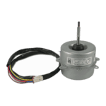
Flotide/MEGA - Heat Pump Fan Motor YKT-32-6-203L - 7024886
118,45 €

Flotide/MEGA - Heat Pump Fan Blade 427mm × 139mm Blue - 7024888
31,95 €

Flotide/MEGA - Heat Pump High Pressure Switch 3.6–4.2 MPa - 7024793
21,95 €

Flotide/MEGA - Low Pressure Switch 0.1–0.3 MPa (Heat Pump A3/32) - 7024791
21,95 €

Flotide/MEGA - LED Display & Controller Board RC-112E (WJL) for Plug & Play A3/32 Heat Pump - 7024894
67,45 €

Flotide/MEGA - Refrigerant Pressure Gauge 63 mm 0–65 bar R32 Rear Connection 1/4" - 7025310
46,45 €

Flotide/MEGA - Heat Pump Water Flow Switch with 32 mm Glue Adapter - 7006471
51,45 €

Descriere
Flotide/MEGA / MEGA Heat Pump Type A On/Off (Type A7/32) exploded view & spare parts
This page presents the full exploded-view diagram and bill of materials for the Flotide/MEGA / MEGA Heat Pump Type A On/Off, model reference A7/32, sold under factory reference 7024511. The diagram covers every major assembly and serviceable component within this on/off R32 pool heat pump, from the outer cabinet panels through to the refrigerant circuit, electrical box, and water-side connections. The Flotide/MEGA Type A range is designed primarily for above-ground swimming pools and uses R32 refrigerant for improved running efficiency. Whether you are a pool owner carrying out routine maintenance or a technician diagnosing a fault, the diagram and parts list on this page will help you pinpoint the exact component you need in minutes.
How to use the numbered diagram to find your part
Every numbered call-out printed on the exploded-view diagram corresponds directly to a numbered row in the parts table below the diagram. Start by identifying the general area of the unit where your fault or wear is visible — for example, the top of the cabinet, the refrigerant circuit, or the electrical enclosure — then locate the relevant call-out number within that zone on the diagram. Once you have the position number, find the matching row in the parts list to obtain the description and, where available, the SKU you need to add to your basket. Bear in mind that some position numbers, such as positions 17 and 18 (both listed as wire clips), appear more than once on the diagram because identical components are used in multiple locations; always check the diagram carefully to confirm which instance of that part you need. Position 25 carries sub-positions — 25.1 and 25.2 — each denoting a different capacitor (25µF and 35µF respectively) housed within the same E-box assembly; these have their own individual SKUs (7010427 and 7010430) and must not be confused with the parent assembly SKU (7024892). Not every component in the diagram has a purchasable SKU listed; structural parts such as the chassis (position 9), column (position 2), or top cover (position 1) are noted for identification purposes but may not be available as standalone spares. If the position number you need does not show a SKU, contact our team for guidance before ordering.
Main replaceable assemblies on the Flotide/MEGA / MEGA Type A7/32
The Type A7/32 is built around several distinct sub-assemblies, each of which contains its own serviceable parts. The fan and motor assembly sits at the top of the unit and comprises the fan motor YKT-32-6-203L (position 5, SKU 7024886) mounted on a motor bracket (position 4), driving a 427 mm × 139 mm fan blade (position 6, SKU 7024888) to draw air across the evaporator. The evaporator (position 3) is the large air-to-refrigerant coil housed within the column (position 2) and protected by the grille (position 8) and front panel (position 7). The refrigerant circuit centres on the compressor KSM135V1VFT (position 10) and is protected by a high-pressure switch rated 3.6–4.2 MPa (position 11, SKU 7024793) and a low-pressure switch rated 0.1–0.3 MPa (position 16, SKU 7024791); a needle valve (position 21) and an R32-rated pressure gauge 0–65 bar (position 22, SKU 7025310) complete the refrigerant-side access points. On the water side, the titanium heat exchanger (position 13) transfers heat to the pool water; water flow is monitored by the water flow switch (position 23, SKU 7006471), while inlet and outlet temperatures are measured by the water-in temperature sensor (position 15) and water-out temperature sensor (position 24). The electrical enclosure (E-box) carries the PC board assembly 803301000201 (position 25, SKU 7024892), including the two capacitors at sub-positions 25.1 and 25.2, and is covered by the E-box cover (position 26); the user interface is the LED display/PCB RC-112E (position 20, SKU 7024894), which provides the on/off and temperature controls visible on the front panel. A repair kit for temperature-related components — including a temperature switch, thermal conductive paste, and wire connectors — is referenced alongside position 26 under SKU 7027177 and is a useful first-order item when fault-finding sensor or overheating issues.
Choosing between variants and pack sizes
Position 25 of this diagram is a clear example of where care is needed: the parent E-box assembly (SKU 7024892) contains two capacitors that are listed separately as sub-positions 25.1 and 25.2. The 25µF capacitor (position 25.1, SKU 7010427) and the 35µF capacitor (position 25.2, SKU 7010430) differ in capacitance rating and connector type — 25.1 is described as a round wired type while 25.2 uses an AMP connector — so ordering the wrong sub-position will result in an incompatible component. Always cross-reference the capacitance value and connector style on your existing part before selecting a SKU. Similarly, the two pressure switches (positions 11 and 16) may look alike but operate at entirely different pressure ranges (high-side versus low-side), and substituting one for the other would prevent the safety circuit from functioning correctly. Where a position in the diagram carries no SKU — such as the titanium heat exchanger (position 13), water temperature sensors (positions 15 and 24), or the compressor (position 10) — please contact us directly, as availability of these components can vary and we can advise on the correct specification before you order.
