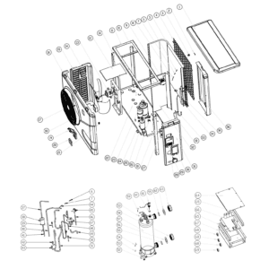
Norsup Heat Pump, Type Inverter (Type Xp21Dcsi) exploded view & spare parts
 Certified online store
 Easy returns within 14 days


Spare parts list

Flotide/MEGA - Ambient Temperature Sensor TH1 with Plug Connector (6×4) - 7020259
15,95 €
Flotide/MEGA - Pipe Temperature Sensor TH2 with 6×4 Plug - 7020260
12,45 €

Hydro-Pro - Heat Pump Fan Motor ZWB378D02B 120W - 7021812
414,45 €

Hydro-Pro - Replacement Fan Blade 554mm × 148mm, 10mm Bore, Anticlockwise - 7021816
99,45 €

Flotide/MEGA - Waterproof Display Box for Inverter Heat Pump (Type Xp05Csie) - 7010543
31,45 €

Flotide/MEGA - Inverter Heat Pump LED Display SHHCLEDV2MM101 - 7021826
226,95 €

Flotide/MEGA - LED Display Panel with Wi-Fi for Inverter Heat Pump (WiFi02iMM011) - 7023600
252,45 €

Flotide/MEGA - Compressor Crankcase Heating Belt 230V 35W 320mm - 7020269
45,45 €

Pressure Gauge 0–55 Bar R410A - 7010518
47,45 €

Flotide/MEGA - Low Pressure Switch 0.1–0.3 MPa (Heat Pump A3/32) - 7024791
21,95 €

Flotide/MEGA - Low Pressure Switch 0.2–0.35 MPa (Inverter Heat Pump Xp05Csie) - 7024792
21,95 €

Flotide/MEGA - Heat Pump High Pressure Switch 3.6–4.2 MPa - 7024793
21,95 €

Flotide/MEGA - Exhaust Temperature Sensor TH3 with Plug (6×4) - 7020261
15,95 €

Flotide/MEGA - PP Pipe Plug ½" Male Thread 10 Bar Black - 0121241
3,45 €

Flotide/MEGA - Water Inlet Temperature Sensor TH6 with Plug (6×4) - 7020263
15,95 €
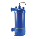
Norsup - Titanium Heat Exchanger for Inverter 21 Heat Pump - 7021831
1.345,95 €

Flotide/MEGA - Water Outlet Temperature Sensor TH5 with Plug (6×4) - 7020262
15,95 €

Flotide/MEGA - Water Flow Switch with VH-2 Plug (9×7 mm) - 7020257
100,95 €

Flotide/MEGA - Inverter Heat Pump PC Board SH0300101-V1.5 - 7021836
1.101,95 €

Descriere
Norsup Heat Pump Inverter (Type XP21DCSI) exploded view & spare parts
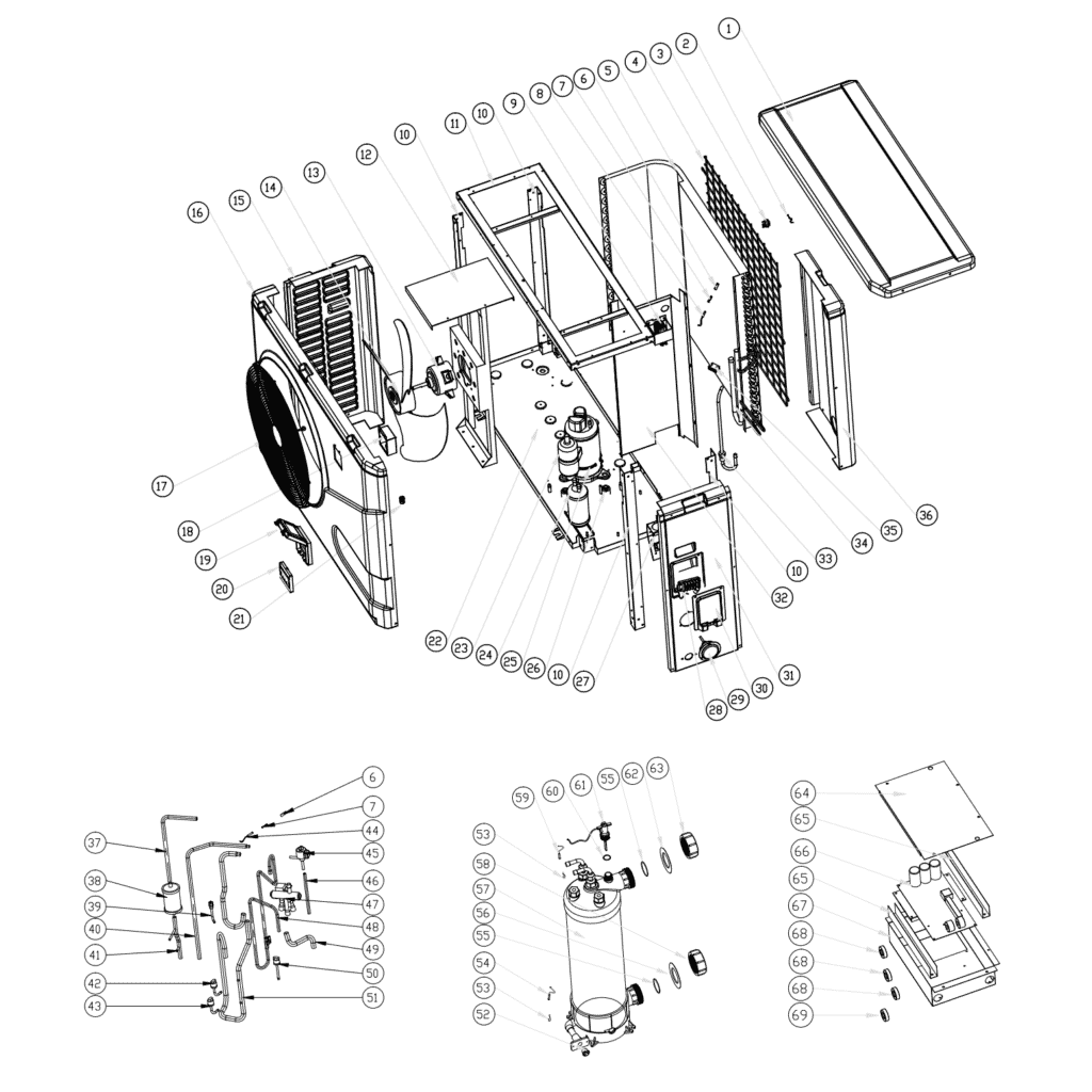
This page covers the complete exploded-view diagram and bill of materials for the Norsup Heat Pump, Type Inverter — factory reference 7021079, commonly identified as the XP21DCSI. The diagram breaks the unit into every numbered component, from the outer casing panels through to the refrigerant circuit and water-side connections. Whether you are a pool owner carrying out routine maintenance or a technician tracing a fault, you will be able to locate the exact part you need within minutes. Where a spare part carries a Norsup SKU, you can add it directly to your basket; positions without a SKU indicate assemblies that are typically replaced as part of a larger service or are not sold separately.
How to use the numbered diagram to find your part
Every call-out number printed on the exploded-view diagram corresponds directly to a numbered row in the parts list below. Start by identifying the area of the unit where the fault or wear has occurred — for example, the top airflow section, the refrigerant circuit, or the water-side connections — then scan the diagram to find the relevant call-out number. Once you have the number, locate the matching row in the table to confirm the part description and, where available, its SKU. Take a moment to read the full description in that row: it often includes critical sizing or specification details (connector type, voltage, pressure rating, dimensions) that are the quickest way to confirm you have the right part. Bear in mind that some call-out numbers appear more than once in the diagram — positions 58 and 63, for instance, both refer to the water connection set (SKU 7014153) fitted at the inlet and outlet sides respectively, and positions 68 and 69 are both listed as magnet rings. Similarly, positions 42 and 43 both describe low-pressure switches but with different pressure ranges, so always cross-reference the specification in the description rather than relying on the position number alone. Lettered suffixes such as 20a and 20b indicate variant options within the same physical location; only one variant will be fitted to any given unit. If you are unsure which variant is installed, check the label on the component itself before ordering.
Main replaceable assemblies on the Norsup XP21DCSI
The XP21DCSI is a full-inverter pool heat pump, meaning its compressor and fan motor speeds vary continuously to match demand rather than simply switching on and off. The airflow assembly at the top of the unit centres on the fan motor (pos. 13 — ZWB378D02B, 120 W, SKU 7021812) and the associated fan blade (pos. 14 — 554 mm × 148 mm, 10 mm anticlockwise bore, SKU 7021816), both of which are individually serviceable. The refrigerant circuit is the heart of the pump: it includes the inverter-driven compressor (pos. 23), a four-way reversing valve (pos. 48) for heating and cooling modes, an electronic expansion valve or EEV (pos. 50), and the evaporator coil (pos. 5) through which ambient air passes. Refrigerant-side protection is provided by a low-pressure switch in two ratings — pos. 42 (0.1–0.3 MPa, SKU 7024791) and pos. 43 (0.2–0.35 MPa, SKU 7024792) — and a high-pressure switch at pos. 45 (3.6–4.2 MPa, SKU 7024793). A compressor heating belt (pos. 25 — 230 V, 35 W, 320 mm, SKU 7020269) protects the compressor during cold-weather standby. On the water side, pool water passes through the titanium heat exchanger (pos. 57, SKU 7021831), which is resistant to salt and chlorine, entering and leaving via water connection sets (pos. 58 and 63, SKU 7014153). Water flow is monitored by the flow switch at pos. 61 (VH-2, 9 × 7 mm plug, SKU 7020257), which prevents the unit from operating without sufficient water movement. The control and display section comprises the main PC board (pos. 66 — SH0300101-V1.5, SKU 7021836), housed inside the electric box (pos. 64), and the waterproof display box (pos. 19, SKU 7010543) with the LED display panel mounted at pos. 20a or 20b. Four temperature sensors report to the control board: the ambient sensor TH1 (pos. 2, SKU 7020259), pipe sensor TH2 (pos. 8, SKU 7020260), exhaust sensor TH3 (pos. 51, SKU 7020261), water-out sensor TH5 (pos. 59, SKU 7020262), and water-in sensor TH6 (pos. 54, SKU 7020263).
Choosing between variants and pack sizes
Position 20 in this diagram comes in two distinct variants — 20a (LED display Inverter SHHCLEDV2MM101, SKU 7021826) and 20b (LED display Inverter WiFi02iMM011, SKU 7023600) — and only one will be fitted to your unit depending on the control configuration it was built with. Before ordering, check the part number printed on the display PCB or confirm with your installation documentation which display type is present. Pressure switches at positions 42 and 43 share the same physical form factor but are calibrated to different cut-out ranges; fitting the wrong rating can cause nuisance trips or, conversely, allow the refrigerant circuit to operate outside its safe envelope, so always match the pressure figures precisely. The water connection sets at positions 58 and 63 carry the same SKU (7014153) and are interchangeable, but do verify the sealing rings — the O-type sealing ring (pos. 55), blue rubber ring (pos. 56), and red rubber ring (pos. 62) — are renewed whenever a water-side connection is disturbed, as reusing old seals is a common cause of post-service leaks. Where a position number carries no SKU, that component is not currently available as an individual spare on this site; if you require such a part, please contact our customer service team who can advise on the best course of action.