



Hydro-Pro Heat Pump (Type 22) exploded view & spare parts
 Certificado loja online
 Devoluções fáceis em até 14 dias


Lista de peças sobressalentes

Hydro-Pro - Painel de controlo LED de ligar/desligar para bomba de calor XK 001 V1 MM011 - 7010515
168,45 €

Hydro-Pro - Painel de controlo LED com Wi-Fi para ligar/desligar a bomba de calor (Tipo WiFi12iMM011) - 7023601
302,95 €
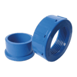
Hydro-Pro - Water Connection Set 50mm Glue Socket (Pack of 2) - 7014127
41,95 €

Pressure Gauge 0–55 Bar R410A - 7010518
47,45 €
Hydro-Pro - Water Connection Set 50mm Glue Socket (Pack of 2) - 7014127
41,95 €

Hydro-Pro - Titanium Heat Exchanger for Type 22 / 22T ABS Heat Pump - 7020788
925,45 €

Flotide/MEGA - Heat Pump Water Flow Switch with 32 mm Glue Adapter - 7006471
51,45 €
Flotide/MEGA - Water Outlet Temperature Sensor T2 - 7010535
10,45 €

Water Inlet Temperature Sensor T1 for Hydro-Pro Heat Pump - 7010534
10,45 €
Pipe Temperature Sensor T3 - 7010533
12,45 €
Hydro-Pro - Replacement PC Board ZK 102 V1 for Heat Pump Type 13 - 7010514
168,45 €

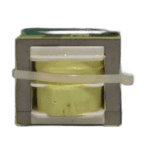
Flotide/MEGA - Heat Pump Transformer ZHL-03/EL-48 - 7010532
26,45 €
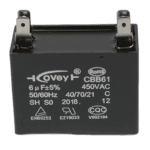
Hydro-Pro - Fan Motor Capacitor 6µF Square Type with Plug Connector - 7019180
9,95 €

Motor Terminal Block 380–400 V / 16 A - 7010526
6,45 €

Contactor Relay CJX9B-25S/D 220–240 V AC for Eco 12 Heat Pump - 7010519
142,95 €

Hydro-Pro - Condensador para motor de bomba de calor, 80 µF, tipo redondo - 7017453
39,95 €

Flotide/MEGA - Low Pressure Switch 0.1–0.3 MPa (Heat Pump A3/32) - 7024791
21,95 €

Flotide/MEGA - Heat Pump High Pressure Switch 3.6–4.2 MPa - 7024793
21,95 €
Hydro-Pro Heat Pump Ambient Temperature Sensor T5 - 7010537
10,45 €

Descrição
I now have enough context. I can see from the search results that the Hydro-Pro Type 22 is a vertical-orientation ABS-cased pool heat pump, and from result 4 I can cross-reference that factory reference 7018527 corresponds to the Type 18 vertical soft-start unit — and 7018528 is the Type 22. However, the product data supplied by the user explicitly lists 7018527 as the parent factory reference for the Type 22 landing page, so I will use that as given without inventing alternative references. I have enough to write accurate, BOM-tied copy now.
Hydro-Pro Heat Pump (Type 22) exploded view & spare parts
This page covers the complete exploded-view diagram and bill of materials for the Hydro-Pro Heat Pump Type 22, a vertical-format ABS-cased swimming pool heat pump listed under factory reference 7018527. The diagram breaks the unit down into every discrete component — from the refrigerant circuit and titanium heat exchanger through to the electrical box, display panel, and water connections — so you can pinpoint exactly what needs replacing without having to remove the unit or call a service agent first. Whether you are a pool owner tackling routine maintenance or a qualified technician working through a fault, you should be able to identify your part and its SKU within a few minutes of consulting the diagram and the table below.
Como utilizar o esquema numerado para encontrar a sua peça
Every numbered call-out printed on the diagram corresponds directly to a row in the parts list beneath it: locate the area of the unit where the suspect component sits, find its call-out number, then read across to the description and SKU columns to confirm the correct part. Once you have the SKU, enter it directly into the search bar at the top of this site to reach the individual product page and add the part to your basket. Be aware that the same part number can appear in more than one location on the diagram — positions 11 and 16, for example, both reference the same water connection set (SKU 7014127), because identical 50 mm glue-socket fittings are used at both the inlet and outlet sides of the unit. Similarly, positions 20 and 22 both describe the titanium exchanger temperature fixing piece; check the diagram carefully to confirm which physical location corresponds to your fault before ordering. Pay particular attention to lettered variants: positions 10a, 10b, and 10c all relate to the control display area but cover three distinct components — the standard LED display (10a), the WiFi-enabled display (10b), and the waterproof housing (10c) — and these are not interchangeable. Finally, note that some positions in this diagram carry no SKU; those structural or refrigerant-circuit components are not currently sold individually, and you should contact us directly if you require guidance on those items.
Main replaceable assemblies on the Hydro-Pro Heat Pump (Type 22)
The Type 22 is built around a small number of principal sub-assemblies that account for the great majority of service calls. The water-side circuit begins at the inlet water connection set (pos. 11), passes through the water flow switch with glue adapter (pos. 19, SKU 7006471), which automatically detects circulation and enables the unit to run, then through the titanium heat exchanger (pos. 18, SKU 7020788), and exits at the outlet water connection set (pos. 16). The titanium heat exchanger is the core of the unit’s heating function and is paired with two temperature sensors: the water-in sensor T1 (pos. 23, SKU 7010534) and the water-out sensor T2 (pos. 21, SKU 7010535), which together allow the control board to regulate output accurately. A third sensor, the pipe temperature sensor T3 (pos. 27, SKU 7010533), monitors the refrigerant-side pipework, while the ambient temperature sensor T5 (pos. 59, SKU 7010537) feeds outdoor air temperature data to the controller. Refrigerant-circuit integrity is protected by the low pressure switch at position 54a (SKU 7024791) and the high pressure switch at position 54b (SKU 7024793); both are safety devices that cut the compressor if pressures fall outside their respective operating ranges, making them important diagnostic components when the unit trips on a pressure fault. The electrical box (pos. 37) houses the main PC board ZK 101 V1 (pos. 39, SKU 7010514), the transformer (pos. 40, SKU 7010532), the relay (pos. 49, SKU 7010519), the terminal block rated at 380–400 V / 16 A (pos. 46, SKU 7010526), and two capacitors — a 6 µF square plug-in type (pos. 41, SKU 7019180) and an 80 µF capacitor (pos. 51, SKU 7017453) — all of which are individually available as spare parts. The user-facing control interface sits at position 10, with the pressure gauge (pos. 14, SKU 7010518) providing a visible check of system pressure without the need for additional instruments.
Choosing between variants and pack sizes
The most important variant choice on this diagram is at position 10, where the display panel comes in two distinct versions: the standard LED On/Off display XK 001 V1 MM011 (pos. 10a, SKU 7010515) and the WiFi-enabled On/Off display WiFi02iMM101 (pos. 10b, SKU 7023601). These two panels use different control protocols and are not substitutable for one another, so before ordering check the label on your existing display or consult your installation documentation to confirm which version your unit shipped with. Position 10c — the waterproof box that houses the display — currently carries no SKU and is not sold separately; if this housing is damaged, contact our team for advice. The pressure switches at positions 54a and 54b are likewise non-interchangeable despite occupying adjacent positions in the diagram: the low-pressure switch (54a) operates in the 0.1–0.3 MPa range, while the high-pressure switch (54b) is rated at 3.6–4.2 MPa, and fitting the wrong unit will result in either nuisance tripping or loss of compressor protection. Where a component description contains a specific reference code — such as the relay at position 49 (Type CJX9B-25S/D, 220–240 V AC) or the transformer at position 40 (ZHL-03/EL-48) — use that code alongside the SKU to double-check that the replacement part matches your unit’s electrical rating before installation.
