



Bomba de calor Flotide/MEGA (Tipo 5) – vista explodida e peças sobressalentes
 Certificado loja online
 Devoluções fáceis em até 14 dias


Lista de peças sobressalentes
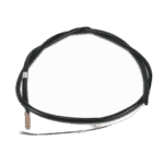
Sensor de temperatura para tubos T3 - 7010533
12,45 €

Sensor de temperatura da entrada de água T1 para a bomba de calor Hydro-Pro - 7010534
10,45 €
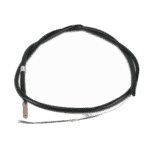
Flotide/MEGA - Sensor de temperatura da saída de água T2 - 7010535
10,45 €

Motor do ventilador da bomba de calor para piscina YDK-18-6 18 W - 7010520
83,95 €

Pá de ventilador de motor 320 mm × 135 mm, orifício de 7 mm, rotação no sentido anti-horário - 7010542
15,95 €

Condensador de funcionamento do motor, 2 µF, tipo encaixável com fichas quadradas - 7010416
3,45 €

Flotide/MEGA - Transformador para bomba de calor ZHL-03/EL-48 - 7010532
26,45 €

Flotide/MEGA - Condensador de arranque de 25 µF para a bomba de piscina SC100 / SC150 - 7010427
57,45 €

Flotide/MEGA - Placa de controlo da bomba de calor ZK 101 V13 - 7019176
218,95 €

Flotide/MEGA - Heat Pump Terminal Block 220–240 V / 16 A (10 mm²) - 7010525
20,95 €

Flotide/MEGA - Interruptor de alta pressão para bomba de calor 3,6–4,2 MPa - 7024793
21,95 €

Flotide/MEGA - Interruptor de baixa pressão 0,1–0,3 MPa (Bomba de calor A3/32) - 7024791
21,95 €

Bloco de terminais para motor 380–400 V / 16 A - 7010526
6,45 €

Manómetro 0–55 bar R410A - 7010518
47,45 €
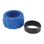
Racorde de compressão para ligação de água de 50 mm - 7014126
41,95 €

Flotide/MEGA - Tampão para tubo de PP com rosca macho de ½", 10 bar, preto - 0121241
3,45 €

Flotide/MEGA - Interruptor de fluxo de água para bomba de calor com adaptador para colagem de 32 mm - 7006471
51,45 €

Flotide/MEGA - Heat Pump LED Display Controller XK 302 V1 - 7019178
125,95 €

Descrição
Bomba de calor Flotide/MEGA (Tipo 5) – vista explodida e peças sobressalentes
This page provides the full exploded-view diagram and numbered bill of materials for the Flotide/MEGA Heat Pump Type 5, sold under factory reference 7018518. The Flotide/MEGA range is manufactured to serve above-ground and domestic pools, using an air-source refrigeration cycle to transfer heat efficiently into pool water. Every component shown in the diagram — from the fan assembly and electrical enclosure through to the refrigerant circuit and water connections — is mapped to a numbered position in the parts list below. Whether you are a pool owner carrying out routine maintenance or a technician diagnosing a fault, you should be able to identify the exact part you need within a few minutes.
Como utilizar o esquema numerado para encontrar a sua peça
Start by locating the area of the unit where the fault or wear has occurred — for example, the electrical box, the refrigerant circuit, or the water connections — then scan that area of the diagram for the relevant call-out number. Each number on the diagram corresponds directly to a numbered row in the parts list, where you will find the part description and, where available, the SKU you need to add to your basket. Note that position 4 is split into lettered variants — 4a, 4b, 4c, and 4d — each representing a different temperature sensor (T1 through T4), so always confirm which sensor location is faulty before ordering. Similarly, take care when a position number appears in more than one place on the diagram, which can happen with common hardware items such as clips (position 22) or wiring clips (position 25). Where a part in the list has no SKU shown, it is either a structural panel, a formed pipe, or another non-serviceable component that is not stocked as a standalone spare. If you are unsure whether a part carries a separate SKU, use the site search with the position description or contact our team before ordering.
Main replaceable assemblies on the Flotide/MEGA Heat Pump (Type 5)
O circuito de ar sits at the heart of the unit’s heat-exchange process and comprises the evaporator (position 6), the fan motor (position 12 — a YDK-18-6 18 W unit), and the 320 mm fan blade (position 13, with a 7 mm anticlockwise-pitch bore). The fan motor and blade are the most commonly replaced moving parts on any air-source heat pump, and both carry dedicated SKUs on this diagram. The circuito de refrigerante includes the compressor (position 33), the electronic expansion valve (position 31), the high-pressure switch rated 3.6–4.2 MPa (position 27), and the low-pressure switch rated 0.1–0.3 MPa (position 30); the two pressure switches are stocked as spares and are frequently the first components to flag a refrigerant-side fault. A single pressure gauge (position 36) provides a visual reference point for circuit pressure. The caixa elétrica (positions 17–25) houses the PC board Flotide/MEGA ZK 101 V13 (position 23), the transformer ZHL-03/EL-48 (position 19), a 2 µF square plug-in capacitor (position 18) for the fan motor, and a 25 µF round wired capacitor (position 21) typically associated with the compressor start circuit; all four of these electrical components carry SKUs. Two terminal blocks are fitted: position 24 for 220–240 V 16 A supply and position 34 for 380–400 V 16 A supply, reflecting the dual-voltage configurations in the Type 5 family. The circuito de água connects to the pool via the water connection set 50 mm compression (position 38), a water flow switch with glued 32 mm adapter (position 42), and the heat exchanger (position 37). The user interface is provided by the LED display Flotide/MEGA XK 302 V1 (position 45), which is a stocked spare part.
Escolher entre variantes e tamanhos de embalagem
The four temperature sensors at position 4 — 4a (pipe sensor T3, SKU 7010533), 4b (water-in sensor T1, SKU 7010534), 4c (water-out sensor T2, SKU 7010535), and 4d (back gas sensor T4, SKU 7010536) — are physically similar but are calibrated and positioned for different measurement points within the refrigerant and water circuits; fitting the wrong sensor to a given port will produce erroneous readings and may trigger unnecessary fault codes. Always cross-reference the sensor position label on the wiring loom or PCB terminal before selecting a variant. The two capacitors at positions 18 and 21 are also distinct: the 2 µF square plug-in type (position 18) and the 25 µF round wired type (position 21) are not interchangeable, and substituting one for the other will damage the motor or compressor circuit it serves. Similarly, the two terminal blocks differ by voltage rating — 220–240 V at position 24 and 380–400 V at position 34 — so confirm your supply voltage before ordering. Where parts such as the plug at position 39 (PP ½” male thread, 10 bar black) are specified with thread size and pressure rating, ensure any replacement matches all three parameters, as thread pitch, diameter, and pressure tolerance all affect sealing integrity.
