



Bomba de calor Flotide/MEGA (Tipo 12) — vista explodida e peças sobressalentes
 Certificado loja online
 Devoluções fáceis em até 14 dias


Lista de peças sobressalentes
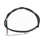
Sensor de temperatura para tubos T3 - 7010533
12,45 €

Sensor de temperatura da entrada de água T1 para a bomba de calor Hydro-Pro - 7010534
10,45 €
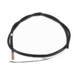
Flotide/MEGA - Sensor de temperatura da saída de água T2 - 7010535
10,45 €

Motor do ventilador YDK-40-6 de 40 W para a bomba de calor Eco 12 - 7010522
151,45 €

Pá do ventilador 420 mm × 148 mm, orifício de 9 mm, rotação no sentido horário - 7010539
43,95 €

Flotide/MEGA - Phase Sequence Relay for Heat Pump Type 12 - 7017965
103,45 €

Condensador de funcionamento do motor, 60 µF, redondo, AMP - 7010433
39,95 €

Condensador para motor do ventilador de bomba de calor, 3 µF, com conector quadrado - 7010417
23,95 €

Flotide/MEGA - Transformador para bomba de calor ZHL-03/EL-48 - 7010532
26,45 €

Flotide/MEGA - Placa de controlo da bomba de calor ZK 102 V13 - 7019177
168,45 €

Flotide/MEGA - Heat Pump Terminal Block 220–240 V / 16 A (10 mm²) - 7010525
20,95 €

Flotide/MEGA - Interruptor de baixa pressão 0,1–0,3 MPa (Bomba de calor A3/32) - 7024791
21,95 €

Flotide/MEGA - Interruptor de alta pressão para bomba de calor 3,6–4,2 MPa - 7024793
21,95 €

Bloco de terminais para motor 380–400 V / 16 A - 7010526
6,45 €
Bloco de terminais para motor 380–400 V / 16 A - 7010526
6,45 €
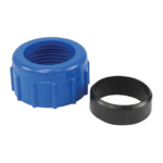
Racorde de compressão para ligação de água de 50 mm - 7014126
41,95 €

Flotide/MEGA - Tampão para tubo de PP com rosca macho de ½", 10 bar, preto - 0121241
3,45 €

Flotide/MEGA - Heat Pump LED Display Controller XK 302 V1 - 7019178
125,95 €

Flotide/MEGA - Interruptor de fluxo de água para bomba de calor com adaptador para colagem de 32 mm - 7006471
51,45 €

Manómetro 0–55 bar R410A - 7010518
47,45 €

Descrição
Flotide/MEGA / MEGA Heat Pump (Type 12) exploded view & spare parts
This page provides the official exploded-view diagram and full bill of materials for the Flotide/MEGA / MEGA Heat Pump Type 12, listed under factory reference 7018521. The diagram covers every serviceable component of this on/off compressor pool heat pump — from the refrigeration circuit and electrical enclosure through to the water-side connections and control electronics. Whether you are a pool owner carrying out routine maintenance or a technician tracing a fault, the numbered diagram and matching parts list below will allow you to identify the exact component you need in a matter of minutes. Always confirm the factory reference on your unit’s data plate before ordering to ensure you are working from the correct diagram.
Como utilizar o esquema numerado para encontrar a sua peça
Every numbered call-out on the diagram corresponds directly to a row in the parts list below; locate the area of the unit where your component sits, then read off the position number shown on the diagram. Once you have the position number, find the matching row in the table to retrieve the SKU, which is what you will need to add the part to your basket. Bear in mind that some position numbers carry a letter suffix — for example, positions 6a, 6b, 6c, and 6d each identify a different temperature sensor (T3, T1, T2, and T4 respectively), so take care to read the full alphanumeric reference rather than stopping at the number alone. Equally, note that positions 34 and 35 share the same description and SKU (7010526 — Terminal block 380–400 V, 16 A); this is intentional and reflects two identical components installed at different locations on the unit, so you may need to order two if both are faulty. Some positions in this diagram do not yet have an individual SKU assigned — these are structural panels, pipework runs, or assemblies that are either not sold separately or are supplied as part of a wider kit; if you require one of these items, please contact us directly. When in doubt, cross-reference the written description in the parts list against the component you are holding, paying particular attention to electrical ratings, physical dimensions, and thread specifications.
Main replaceable assemblies on the Flotide/MEGA / MEGA Heat Pump (Type 12)
O temperature-sensing group (positions 6a–6d) comprises four individual NTC-style sensors covering the pipe temperature T3, water-in T1, water-out T2, and back-gas T4; each is stocked as a separate SKU (7010533–7010536) because a single faulty sensor is among the most common causes of error codes and compressor lock-out. The montagem do lado do ar centres on the evaporator (position 8) working in conjunction with the 40 W fan motor YDK-40-6 at position 11 (SKU 7010522) and the 420 mm × 148 mm clockwise fan blade at position 12 (SKU 7010539); when the unit runs noisily or shows reduced heating performance, these two parts are the first to inspect. The refrigeration circuit includes the compressor (position 38), the electronic expansion valve (position 31), the low-pressure switch rated 0.1–0.3 MPa at position 29 (SKU 7024791), and the high-pressure switch rated 3.6–4.2 MPa at position 30 (SKU 7024793); these pressure switches are safety devices and should be replaced like-for-like to maintain correct cut-out thresholds. The caixa elétrica (position 26) houses the PC board Flotide/MEGA ZK 102 V13 at position 22 (SKU 7019177), the transformer ZHL-03/EL-48 at position 21 (SKU 7010532), the phase sequence relay at position 17 (SKU 7017965), and two capacitors — a 60 µF unit at position 19 (SKU 7010433) and a 3 µF square-plug type at position 20 (SKU 7010417). The user-facing LED display, Flotide/MEGA XK 302 V1 at position 44 (SKU 7019178), sits behind the display cover (position 45) and communicates with the main board. On the water side, the heat exchanger at position 40 transfers refrigerant energy to pool water, while the water flow switch with glue adapter 32 mm at position 46 (SKU 7006471) prevents the unit from running without adequate flow — a key protection component that should be tested seasonally. The conjunto de ligação à água at position 36 (SKU 7014126) provides the 50 mm compression fittings that link the heat pump to the pool’s return and feed lines, and is supplied as a complete set.
Escolher entre variantes e tamanhos de embalagem
As noted above, the position 6 sensors are split into four lettered variants — 6a, 6b, 6c, and 6d — each with its own SKU and a specific location in the refrigerant or water circuit; fitting the wrong sensor in the wrong location will result in incorrect temperature readings and potential fault codes, so always order by the full alphanumeric position reference rather than by position 6 alone. The two terminal blocks in this unit come in two distinct voltage ratings: the 220–240 V 16 A block at position 23 (SKU 7010525) and the 380–400 V 16 A block at positions 34 and 35 (SKU 7010526); these are not interchangeable, and fitting a lower-rated block on a higher-voltage circuit presents a safety risk, so confirm your supply voltage before ordering. Similarly, the capacitors at positions 19 and 20 differ significantly in value (60 µF versus 3 µF) and in physical form factor; always quote the SKU rather than relying solely on the capacitance value, as the housing type and terminal configuration also matter for a correct fit. Where a component such as the plug at position 43 (SKU 0121241) carries a thread specification — in this case ½″ male thread rated to 10 bar — verify that the thread form on your existing pipework matches before fitting, as both BSP and NPT ½″ threads exist in the field and are not compatible.
