



Norsup-warmtepomp, type Pv Inverter (type P31Tv/32) – exploded view en reserveonderdelen
 Gecertificeerd webwinkel
 Eenvoudig retourneren binnen 14 dagen


Lijst met reserveonderdelen

Norsup - Ventilatormotor 250 W ZWS250-A51 - 7027687
450,95 €
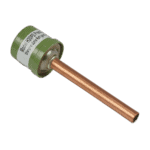
Hydro-Pro - Hogedrukschakelaar 3,2 MPa / 4,4 MPa (groen) voor warmtepomp type P - 7011008
27,95 €

Hydro-Pro - Lagedrukschakelaar voor warmtepompen 0,3 MPa / 0,15 MPa - 7011009
27,95 €

Flotide/MEGA - Waterstroomschakelaar voor warmtepompen met 32 mm lijmadapter - 7006471
51,45 €

Norsup - Warmtewisselaar voor P31V/32- en P31TV/32-warmtepompen - 7027694
634,95 €

Norsup - Aluminium ventilatorblad Ø 600 mm × 150 mm, tegen de klok in (12 mm asgat) - 7027689
195,45 €

Norsup - Module voor ventilatorsnelheidsregeling 20000-430228 + 35005-310617 - 7027685
195,45 €

Norsup - Omvormerkaart 2AC32I07WM1 voor PV-warmtepomp P21TV/32 - 7027680
1.191,45 €

Hydro-Pro - 2-polige draadverbinding, wit, 450 V / 4 mm² - 7011019
4,95 €

Beschrijving
Norsup Heat Pump PV Inverter (Type P31TV/32) exploded view & spare parts
This page covers the full exploded-view diagram and bill of materials for the Norsup swimming pool heat pump Type P31TV/32, sold under factory reference 7026972. The P31TV/32 is the full-inverter, vertical-discharge model in Norsup’s R32 refrigerant PV range, sitting alongside the non-turbo P31V/32 sibling; the heat exchanger at position 20 is shared between both variants. Using R32 refrigerant and a variable-speed inverter-driven compressor, this unit modulates its heating output to match prevailing conditions rather than cycling on and off at a fixed capacity. Locate the numbered call-out on the diagram that corresponds to the component you need, then match it to the parts list below to find the correct SKU — most visitors identify their part within a few minutes.
Hoe u het genummerde schema kunt gebruiken om uw onderdeel te vinden
Every circled number printed on the exploded-view diagram corresponds directly to a numbered row in the parts list table beneath it. The most efficient approach is to start by identifying the broad area of the heat pump where the fault or wear has occurred — for example, the electrical box, the refrigerant circuit, or the fan assembly — then scan only the positions within that zone rather than reading through all 49 rows. Once you have the position number, find the matching row in the table: if a SKU is shown, that part is individually orderable through this page; if the SKU column is blank, the component is currently not offered as a standalone spare. Note that positions 25 and 26 both describe a conduit bend, and positions 41 and 48 both describe a relay — these are separate physical items that appear more than once in the unit, so double-check the diagram to confirm which location applies to your repair. Position 49 is a support row that groups several accessories — including temperature sensors, a pressure gauge, a Wi-Fi module, a winter cover, and drain hose fittings — each carrying its own individual SKU listed within the description field rather than the position SKU column; refer to those part numbers directly when ordering accessories. Always cross-reference the written description against what you can see on the unit, since part names such as “needle valve (1)” at position 10 and “needle valve (2)” at position 11 distinguish physically identical-looking components solely by their location in the refrigerant circuit.
Main replaceable assemblies on the Norsup P31TV/32
The fan assembly at the top of the unit comprises three separately orderable components: the fan motor (position 1, SKU 7027687), the fan blade (position 33, SKU 7027689), and the fan speed control module (position 39, SKU 7027685). The fan blade specified for this model is a 600 mm diameter, 150 mm pitch, 12 mm bore, anti-clockwise unit, so confirming rotation direction before ordering is important. The refrigerant circuit is built around the inverter-driven compressor (position 22, model SVB220FLGMC-L), supported by a high-pressure switch rated 3.2 MPa cut-out / 4.4 MPa reset (position 6, SKU 7011008) and a low-pressure switch rated 0.3 MPa / 0.15 MPa (position 7, SKU 7011009); these switches are the first components to check when the unit trips on a pressure fault. The titanium heat exchanger at position 20 (SKU 7027694) is listed as compatible with both the P31V/32 and P31TV/32, making it the correct replacement for either model in this size class. Water-side protection is provided by the flow switch at position 12 (SKU 7006471), a 32 mm glued-socket unit that prevents the compressor from running without adequate water flow. The electrical box contains the main PC1004 PCB controller (position 40, SKU 7027675), the inverter driver board (position 42, SKU 7027680), and the EMC filter plate (position 45, SKU 7027683); these three boards together govern the inverter operation and should be diagnosed in sequence before replacing individual components. The user interface is the colourful display panel at position 15 (SKU 7024942), factory reference 20000-430176-8200047, mounted on the front panel at position 14. Wiring connectors — the 5-way connector at position 38 (SKU 7011025) and the 2-way connector at position 47 (SKU 7011019) — are inexpensive but critical items worth inspecting whenever the electrical box is opened for another repair.
Kiezen tussen varianten en verpakkingsgroottes
The P31TV/32 diagram does not carry lettered sub-variants (such as “a” / “b”) within individual position numbers, so each position maps to a single defined component; however, the description at position 49 bundles multiple accessory lines that carry distinct SKUs and must each be ordered individually. When ordering the water flow switch at position 12, confirm that your pipework accepts a 32 mm glued socket, as this unit is not directly interchangeable with threaded or larger-bore alternatives without an adapter. The fan blade at position 33 is defined by four parameters — diameter (600 mm), pitch (150 mm), bore (12 mm), and rotation direction (anti-clockwise) — and substituting a blade with the correct diameter but wrong rotation direction will reduce airflow significantly, so verify all four before purchasing. For small consumable connectors such as the 2-way and 5-way wire connectors at positions 47 and 38, check whether your fault affects a single connector or a run of identical connectors along the same harness, as ordering one at a time can slow a repair that involves multiple deteriorated joints.
