



Hydro-Pro-warmtepomp, type P aan/uit (type P23T/32) – opengewerkte tekening en reserveonderdelen
 Gecertificeerd webwinkel
 Eenvoudig retourneren binnen 14 dagen


Lijst met reserveonderdelen

Hydro-Pro - LCD-touchscreenmodule met wifi (type P aan/uit) - 7016596
217,95 €

Hydro-Pro - Ingebouwde koelmiddeldrukmeter 0–65 bar (R32) - 7024868
52,45 €

Flotide/MEGA - Waterstroomschakelaar voor warmtepompen met 32 mm lijmadapter - 7006471
51,45 €

Hydro-Pro - Titanium warmtewisselaar voor warmtepomp P23T/32 - 7024877
582,45 €

Hydro-Pro - Lagedrukschakelaar voor warmtepompen 0,3 MPa / 0,15 MPa - 7011009
27,95 €
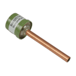
Hydro-Pro - Hogedrukschakelaar 3,2 MPa / 4,4 MPa (groen) voor warmtepomp type P - 7011008
27,95 €

Hydro-Pro - Messing hogedruknaaldklep 20000-140150 - 7006466
9,45 €

Hydro-Pro - Axiaalventilatormotor 35 W YDK35-6 - 7024869
112,95 €

Hydro-Pro - Vervangingsventilatorblad 440 mm, 4 bladen, tegen de klok in draaiend (warmtepomp type P8/32) - 7011024
44,95 €
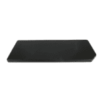
Hydro-Pro - Bovenklep voor warmtepomp 1115 x 430 mm (type P aan/uit) - 7033048
120,45 €

Hydro-Pro - PC 1001-bedieningsunit voor warmtepompen uit de P/32-serie (P23T/32) - 7027827
142,95 €

Hydro-Pro - PC 1001 elektronische regelaar voor warmtepompen uit de P-serie (P6/32) - 7026538
180,45 €

Condensator voor ventilatormotor van warmtepomp, 3 µF, vierkant insteektype - 7010417
23,95 €

Hydro-Pro - 2-polige draadverbinding, wit, 450 V / 4 mm² - 7011019
4,95 €

Hydro-Pro - Verlengkabel van 10 meter met behuizing voor de regelaar van een warmtepomp van het type P (aan/uit) (wit) - 7025168
52,45 €

Beschrijving
Hydro-Pro Heat Pump Type P On/Off (P23T/32) exploded view & spare parts
Op deze pagina vindt u de volledige exploded view en de genummerde stuklijst voor de Hydro-Pro Heat Pump, Type P On/Off, model P23T/32, Hydro-Pro factory reference 7024530. The P23T/32 is the three-phase, 400 V variant within the Hydro-Pro Type P On/Off family, sharing the same physical platform as the single-phase P23/32 but wired for three-phase supply and rated for pools up to 80 m³. The diagram covers every major assembly from the evaporator and refrigerant circuit through to the electrical enclosure and external casing panels. Use the numbered call-outs alongside the parts list below to identify exactly the component you need, so you can confirm the correct SKU and get your heat pump back up and running with minimal delay.
Hoe u het genummerde schema kunt gebruiken om uw onderdeel te vinden
Every circled number printed on the diagram corresponds directly to a numbered row in the parts list table below the image — locate the area of the unit where the fault or wear is visible, then find the matching call-out number on the diagram. Once you have the position number, cross-reference it to the parts list to read the full description and, where available, the SKU you need to add to your basket. Bear in mind that some numbers appear in more than one location on the diagram; this is intentional where the same component (for instance, a fastener or a panel clip) is used in several places on the chassis, so check all instances before ordering quantity. Pay close attention to lettered suffixes: position 30 in this diagram carries two variants — 30a en 30b — which are different PC 1001 controller boards for different sub-variants of the unit, and selecting the wrong one will result in an incompatible board. Position 36 is a grouped accessories row covering several ancillary items (sensors, rubber feet, union couplers) that do not each carry their own individual position number in this diagram. If the SKU column for a position shows no part number, that component is not currently sold separately and you should contact us for guidance before attempting a repair.
Main replaceable assemblies on the Hydro-Pro Type P On/Off (P23T/32)
De control and user-interface group sits at the top of the unit and consists of the LCD Wi-Fi touch-screen display assembly (position 1, SKU 7016596) and the PC 1001 controller board mounted inside the electrical enclosure (position 30a/30b, SKUs 7027827 and 7026538 respectively); together these govern all temperature, defrost, and on/off logic. The koelcircuit is the heart of the heat pump: the rotary compressor (position 6, QXFS-H49sN345A) drives refrigerant through the 4-way reverse valve (position 16), the evaporator coil (position 27), and the titanium heat exchanger (position 8, SKU 7024877), which is the component directly responsible for transferring heat into your pool water and is specifically rated for the P23/32 platform. Circuit integrity is monitored by the low-pressure switch at 0.3 MPa / 0.15 MPa (position 13, SKU 7011009) and the high-pressure switch at 3.2 MPa / 4.4 MPa (position 14, SKU 7011008); either switch can trigger a fault lockout if the refrigerant charge is low or if there is a blockage. Refrigerant pressure can be read via the 0–65 bar gas pressure meter (position 3, SKU 7024868) fitted to the refrigerant service port. The onderdelen aan de waterzijde include the water flow switch with 32 mm glue adapter (position 7, SKU 7006471), which senses circulation from the pool pump and prevents the compressor from running dry, and the brass needle valve (position 15, SKU 7006466) used to regulate or isolate water flow during servicing. The air-handling group comprises the axial fan motor 45 W YDK45-6 (position 17, SKU 7024869), the four-bladed 440 mm fan blade with anti-clockwise rotation and a 10 mm bore (position 18, SKU 7011024), the fan motor bracket (position 22), and the fan motor guard net (position 19). The schakelkast (position 33) houses the AC contactors for the compressor (position 24) and water pump (position 31), the 3 µF square plug-in capacitor (position 32, SKU 7010417), the 2-way wire connector (position 34, SKU 7011019), and the 5-way wire connector (position 35, SKU 7011025). The external casing is made up of the front panel (position 9), right panel (position 2), back panel (position 20), middle separation panel (position 4), supporting panel (position 23), and the top lid measuring 1115 × 430 mm (position 21, SKU 7033048).
Kiezen tussen varianten en verpakkingsgroottes
The most consequential variant choice on this diagram is between the two controller boards at position 30. Position 30a (SKU 7027827) carries the factory designation for the P23T/32 sub-variant specifically in its firmware reference (82300022-35005-310457 P23T/32), while position 30b (SKU 7026538) is the broader P-series version without that sub-variant suffix; fitting the wrong board may cause the unit to run with incorrect pressure thresholds or display parameters, so confirm your exact unit variant before ordering. For the fan blade at position 18, the specification is precise — 440 mm diameter, 152 mm pitch, 10 mm shaft bore, four blades, anti-clockwise rotation — and substituting a blade with a different pitch or bore diameter will result in reduced airflow or mechanical interference with the motor shaft. The pressure switches at positions 13 and 14 are calibrated to specific cut-in and cut-out pressures and are not interchangeable with switches from other heat pump models, even if they appear physically similar. Where accessories are grouped under position 36 (temperature sensors, rubber feet, union couplers), each item has its own individual SKU referenced in the description; take care to order only the specific sub-item you require rather than treating position 36 as a single assembly.
