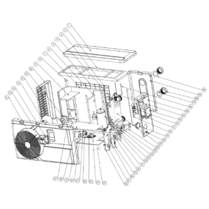
Pompa di calore Hydro-Pro (Tipo 5): vista esplosa e ricambi
 Certificato negozio online
 Resi facili entro 14 giorni


Elenco dei ricambi
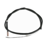
Sensore di temperatura ambiente per pompa di calore Hydro-Pro T5 - 7010537
10,45 €

Sensore di temperatura dell'acqua in entrata T1 per pompa di calore Hydro-Pro - 7010534
10,45 €
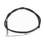
Flotide/MEGA - Sensore di temperatura dell'acqua in uscita T2 - 7010535
10,45 €

Motore del ventilatore per pompa di calore per piscina YDK-25-6 25 W - 7010521
92,45 €

Pala della ventola per pompa di calore da piscina 400 mm × 118 mm, foro da 8 mm, rotazione antioraria - 7010538
31,45 €

Hydro-Pro - Pannello di controllo LED per l'accensione/spegnimento della pompa di calore XK 001 V1 MM011 - 7010515
168,45 €

Hydro-Pro - Pannello di controllo LED WiFi per l'accensione/spegnimento della pompa di calore (tipo WiFi12iMM011) - 7023601
302,95 €

Flotide/MEGA - Trasformatore per pompa di calore ZHL-03/EL-48 - 7010532
26,45 €

Flotide/MEGA - Condensatore di avviamento da 25 µF per pompa da piscina SC100 / SC150 - 7010427
57,45 €

Condensatore di avviamento motore da 2 µF, tipo a innesto quadrato - 7010416
3,45 €

Hydro-Pro - Scheda di controllo per pompa di calore ZK 101 V1 - 7010513
168,45 €

Flotide/MEGA - Pressostato di bassa pressione 0,1–0,3 MPa (pompa di calore A3/32) - 7024791
21,95 €

Flotide/MEGA - Pressostato di alta pressione per pompa di calore 3,6–4,2 MPa - 7024793
21,95 €
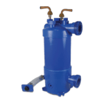
Hydro-Pro - Scambiatore di calore in titanio per pompa di calore ABS tipo 5 - 7020783
378,45 €

Flotide/MEGA - Tappo per tubi in PP, filettatura maschio da ½", 10 bar, nero - 0121241
3,45 €

Manometro 0–55 bar R410A - 7010518
47,45 €
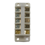
Hydro-Pro - Morsettiera per pompa di calore 220–240 V / 32 A (16 mm²) - 7010527
20,95 €

Flotide/MEGA - Interruttore di flusso per pompe di calore con adattatore a incollare da 32 mm - 7006471
51,45 €
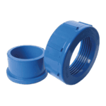
Hydro-Pro - Set di raccordi idraulici da 50 mm con attacco a incollaggio (confezione da 2) - 7014127
41,95 €

Descrizione
Pompa di calore Hydro-Pro (Tipo 5): vista esplosa e ricambi
This page provides the official exploded-view diagram and full bill of materials for the Hydro-Pro Heat Pump (Type 5), carried under Hydro-Pro factory reference 7018522. The diagram covers the complete unit — from the air-side components (evaporator, fan, and grilles) through to the refrigerant circuit and the water-side plumbing connections. Whether you are a pool owner tracing a fault or a technician ordering a replacement part, every numbered call-out on the drawing maps directly to a row in the parts list below, so you can confirm the correct SKU in minutes.
Come utilizzare lo schema numerato per individuare il proprio componente
Start by locating the area of the unit where the fault or wear is visible — for example, the electrical enclosure, the fan assembly, or the water connections — then find the corresponding call-out number on the diagram. Each number in the diagram matches exactly one row in the parts table, giving you the part description and, where available, the poolparthub.com SKU to add directly to your basket. Pay close attention to lettered suffixes: position 3, for instance, is split into 3a (ambient temperature sensor T5), 3b (water-in sensor T1), 3c (water-out sensor T2), and 3d (pipe sensor T3) — four physically different sensors sharing the same position group. Similarly, position 15 splits into 15a (the standard XK 001 V1 display) and 15b (the Wi-Fi enabled WiFi02i display); fitting the wrong variant will result in an incompatible control board connection. Some positions — such as structural panels, pipework, and rubber seals — appear in the diagram for reference but are listed without a direct SKU, meaning they are either non-serviceable as individual items or must be sourced as part of a sub-assembly. If a position shows no SKU, contact our team before ordering.
Main replaceable assemblies on the Hydro-Pro Heat Pump (Type 5)
Il temperature sensor group (positions 3a–3d) is one of the most frequently replaced sections of this heat pump. The four sensors monitor ambient air, water-in, water-out, and refrigerant pipe temperatures respectively, and each has its own SKU to ensure an exact match. The gruppo ventola comprises the fan motor at position 11 (YDK-25-6, 25 W) and the 400 mm × 118 mm fan blade at position 12 (8 mm shaft hole, anticlockwise rotation) — both are individually available and should always be inspected together when diagnosing poor airflow or excessive noise. The sezione di controllo e visualizzazione includes the PC board at position 23 (ZK 101 V1, SKU 7010513), the transformer at position 19 (ZHL-03/EL-48, SKU 7010532), and the LED display panel at position 15a or 15b depending on whether the unit was supplied with standard or Wi-Fi control. Two capacitors serve different functions within the electrical box: the 25 µF round wired type at position 20 (SKU 7010427) and the 2 µF square plugged type at position 22 (SKU 7010416) — confirm which is faulty before ordering, as they are not interchangeable. The circuito del refrigerante is anchored by the titanium heat exchanger at position 37 (SKU 7020783), which transfers heat to the pool water and is resistant to chlorine and salt water; the high-pressure switch at position 30 (3.6–4.2 MPa, SKU 7024793) and the low-pressure switch at position 28 (0.1–0.3 MPa, SKU 7024791) protect the circuit from over- or under-pressure conditions. On the water side, the flow switch at position 44 (32 mm glue adapter, SKU 7006471) prevents the unit from running without adequate water flow, and the set di allacciamento idraulico at position 48 (50 mm glue socket, SKU 7014127) provides the primary plumbing interface to the pool pipework. The pressure gauge at position 39 (SKU 7010518) and the terminal block at position 42 (220–240 V, 32 A / 16 mm², SKU 7010527) round out the individually stocked serviceable parts.
Scelta tra varianti e formati di confezione
The most important variant decision on this unit is the display panel at position 15. Position 15a (SKU 7010515) is the standard LED On/Off panel referenced as XK 001 V1 MM011, while position 15b (SKU 7023601) is the Wi-Fi enabled version referenced as WiFi02i MM101. These two panels use different communication protocols with the PC board at position 23, so you must match the replacement to whichever display variant was fitted at the factory. For the capacitors, the two types differ in capacitance, physical format, and connection method — the 25 µF unit (pos. 20) uses a round wired format, whereas the 2 µF unit (pos. 22) is square and plugged; mixing them up will prevent the motor or compressor circuit from starting correctly. When ordering the PP plug at position 38 (½" male thread, 10 bar, SKU 0121241), confirm the thread pitch and material are compatible with your existing plumbing fittings before installation. For any position where lettered sub-variants exist, always cross-reference both the position number and the full part description against the label or data plate on your unit, as the Type 5 designation covers a single configuration but the lettered suffixes reflect real physical differences that affect fitment.