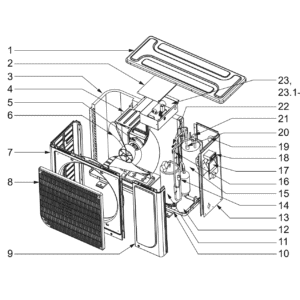
Flotide/MEGA Heat Pump , Type A On/Off (Type A13/32) exploded view & spare parts
 Certificato negozio online
 Resi facili entro 14 giorni


Elenco dei ricambi

Flotide/MEGA - Heat Pump Fan Motor YDK60-6H - 7024887
152,95 €

Flotide/MEGA - Heat Pump Fan Blade 522 mm × 140 mm - 7024889
100,95 €

Flotide/MEGA - Pressostato di alta pressione per pompa di calore 3,6–4,2 MPa - 7024793
21,95 €

Flotide/MEGA - Pressostato di bassa pressione 0,1–0,3 MPa (pompa di calore A3/32) - 7024791
21,95 €

Flotide/MEGA - Display a LED e scheda di controllo RC-112E (WJL) per pompa di calore Plug & Play A3/32 - 7024894
67,45 €

Flotide/MEGA - Manometro per refrigerante 63 mm 0–65 bar R32 Attacco posteriore 1/4" - 7025310
46,45 €

Flotide/MEGA - Interruttore di flusso per pompe di calore con adattatore a incollare da 32 mm - 7006471
51,45 €

Descrizione
Flotide/MEGA / MEGA Heat Pump Type A On/Off (Type A13/32) exploded view & spare parts
This page provides the official exploded-view diagram and full bill of materials for the Flotide/MEGA / MEGA swimming pool heat pump, Type A On/Off, covering the A13/32 variant sold under factory reference 7024513. The A-series uses traditional on/off compressor technology — simple, reliable, and well-proven over millions of installations. The range is available in a choice of output sizes — 4.5 kW, 6.6 kW, 9.6 kW, and 12.5 kW — all sharing the same cabinet architecture and the same spare-parts numbering shown in this diagram. Whether you are a pool owner carrying out seasonal maintenance or a technician diagnosing a fault on site, the numbered call-outs and corresponding SKUs on this page will help you identify the exact part you need in minutes.
Come utilizzare lo schema numerato per individuare il proprio componente
Every numbered call-out printed on the exploded-view diagram corresponds directly to a row in the parts table below it. Start by looking at the physical area of the heat pump where your fault or wear is located — for example, the air-circuit at the top of the cabinet, the refrigerant circuit on the right-hand side, or the water-circuit at the base. Once you have narrowed down the area, find the matching position number on the diagram and cross-reference it with the parts table to retrieve the item description and, where available, the SKU. Only positions that carry a specific SKU can be ordered directly through this page; positions shown without a SKU are structural or enclosure components that are not supplied as standalone service parts. Bear in mind that some fasteners and brackets may share the same position number across several locations in the diagram, so check the written description carefully before adding an item to your basket. Position 23 in particular covers the PC board / E-box assembly (SKU 7024893) and is broken into lettered sub-positions — 23.1, 23.2, and 23.4 — each representing a distinct electrical component that can be replaced individually without purchasing the full assembly. If you are unsure whether you need the complete assembly or a single sub-component, read the sub-position descriptions in full before ordering.
Main replaceable assemblies on the Flotide/MEGA / MEGA Type A On/Off
The heat pump is built around five functional sub-systems, and the diagram reflects each one clearly. The circuito dell'aria sits at the top of the unit and comprises the fan motor YDK60-6H (position 5, SKU 7024887) and the 522 mm × 140 mm fan blade (position 6, SKU 7024889), both mounted to the motor bracket at position 4 and drawing ambient air across the evaporator at position 3. The heat exchanger is made from titanium material, making it resistant to salt and chlorine; this is the titanium heat-exchanger at position 15, which transfers energy from the refrigerant into the pool water. The circuito del refrigerante is protected by two pressure switches: the high-pressure switch rated 3.6–4.2 MPa at position 14 (SKU 7024793) and the low-pressure switch rated 0.1–0.3 MPa at position 16 (SKU 7024791); the compressor itself (QXF-F24F050) occupies position 11. A pressure gauge for R32 refrigerant, rated 0–65 bar, is listed at position 19 (SKU 7025310) and gives a quick visual check of system pressure. The circuito idraulico is monitored by the water flow switch at position 21 (SKU 7006471), which prevents the unit from running without adequate flow, and the water-out temperature sensor at position 20. The electrical and control system centres on the LED display / PCB RC-112E (WJL) at position 18 (SKU 7024894) and the full PC board / E-box assembly at position 23 (SKU 7024893). The enclosure — top cover (position 1), front panel (position 7), grille (position 8), right panels (positions 9 and 13), chassis (position 10), and handle (position 17) — completes the cabinet and is shown in the diagram for orientation purposes.
Scelta tra varianti e formati di confezione
Position 23 is the most important example of sub-variant ordering on this diagram. The full PC board / E-box assembly (23, SKU 7024893) can be purchased as a complete unit, but three individual sub-components are also available separately: the round 55 µF capacitor (sub-position 23.1, SKU 7024891), the square plug-in 3.5 µF capacitor (sub-position 23.2, SKU 7024890), and the water-in temperature sensor (sub-position 23.4, SKU 7011007). Always confirm which sub-position you need before ordering, because the two capacitors differ in both capacitance value and physical form factor — fitting the wrong one will prevent the fan motor or compressor from starting correctly. If you are carrying out a general service rather than a targeted repair, consider the dedicated repair kit for the Flotide/MEGA Type A (SKU 7027177), which bundles a temperature switch, thermally conductive paste, and wire connectors into a single order. For any position listed without a SKU, please contact us directly, as enclosure panels and structural components are assessed for supply on a case-by-case basis.