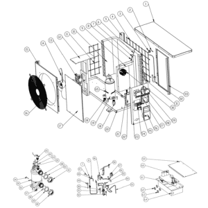
Flotide/MEGA Heat Pump, Type Inverter (Type Xp09Csie) exploded view & spare parts
 Tanúsított online áruház
 Egyszerű visszaküldés 14 nap


Pótalkatrész-lista

Flotide/MEGA - Ambient Temperature Sensor TH1 with Plug Connector (6×4) - 7020259
15,95 €
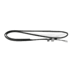
Flotide/MEGA - Pipe Temperature Sensor TH2 with 6×4 Plug - 7020260
12,45 €

Pool Heat Pump Fan Motor YDK-25-6 25W - 7010521
92,45 €

Pool Heat Pump Fan Blade 400mm × 118mm, 8mm Bore, Counterclockwise - 7010538
31,45 €

Flotide/MEGA - Waterproof Display Box for Inverter Heat Pump (Type Xp05Csie) - 7010543
31,45 €

Flotide/MEGA - Inverter Heat Pump LED Display SHHCLEDV2MM101 - 7021826
226,95 €

Flotide/MEGA - LED Display Panel with Wi-Fi for Inverter Heat Pump (WiFi02iMM011) - 7023600
252,45 €

Pressure Gauge 0–55 Bar R410A - 7010518
47,45 €

Flotide/MEGA - Water Inlet Temperature Sensor TH6 with Plug (6×4) - 7020263
15,95 €

Flotide/MEGA - Titanium Heat Exchanger for Hydro-S Inverter 9 Heat Pump - 7021846
756,95 €

Flotide/MEGA - PP Pipe Plug ½" Male Thread 10 Bar Black - 0121241
3,45 €

Flotide/MEGA - Water Outlet Temperature Sensor TH5 with Plug (6×4) - 7020262
15,95 €

Flotide/MEGA - Water Flow Switch with VH-2 Plug (9×7 mm) - 7020257
100,95 €

Flotide/MEGA - Exhaust Temperature Sensor TH3 with Plug (6×4) - 7020261
15,95 €

Flotide/MEGA - Heat Pump High Pressure Switch 3.6–4.2 MPa - 7024793
21,95 €

Flotide/MEGA - Low Pressure Switch 0.1–0.3 MPa (Heat Pump A3/32) - 7024791
21,95 €

Flotide/MEGA - Low Pressure Switch 0.2–0.35 MPa (Inverter Heat Pump Xp05Csie) - 7024792
21,95 €

Flotide/MEGA - Inverter Heat Pump Control Board SH0150101-V1.5 - 7021834
559,45 €

Motor Run Capacitor 2 µF Square Plug-in Type - 7010416
3,45 €

Flotide/MEGA - Compressor Crankcase Heater Belt 230V 35W 340mm - 7020267
44,45 €

Leírás
Flotide/MEGA Heat Pump Inverter (Type Xp09Csie) exploded view & spare parts
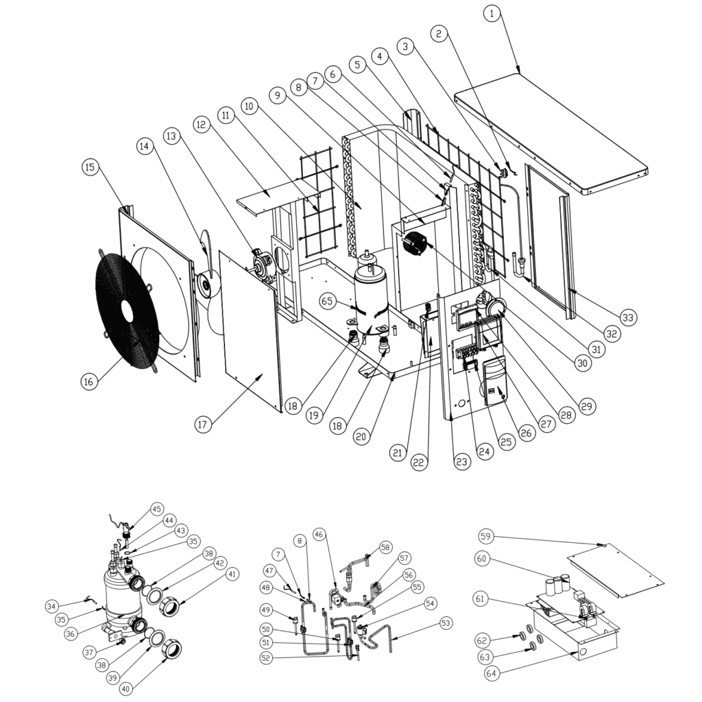
This page provides the full exploded-view diagram and numbered bill of materials (BOM) for the Flotide/MEGA Heat Pump, Type Inverter, model designation Xp09Csie, sold under factory reference 7021086. The diagram covers every serviceable component of this inverter-driven swimming pool heat pump — from the outer casing panels and air-circuit parts through to the refrigerant circuit, electrical box, water connections, and control electronics. Whether you are a pool owner carrying out routine maintenance or a qualified technician tracing a fault, the diagram and parts list below will help you pinpoint the exact part you need in minutes. Use the position numbers printed on the diagram alongside the SKUs listed in the table to go straight to the correct product page on poolparthub.com.
Hogyan lehet a számozott ábra segítségével megtalálni az alkatrészt?
Every numbered call-out on the exploded-view diagram corresponds directly to a row in the parts table below — locate the area of the unit you are working on first (for example, the water-circuit side or the electrical box), then find the relevant call-out number, and finally match that number to the SKU column to reach the correct product page. Where a SKU appears in the table, the part is available to order directly; positions without a SKU are structural or refrigerant-circuit items that are not currently sold separately. Pay close attention to positions that share the same number: for example, positions 40 and 41 both describe the Water connection set (SKU 7014153) because the same set is used at two separate locations on the unit — ordering one line covers one set, so check how many your installation requires. Lettered variants deserve particular attention: positions 28a és 28b are two distinct LED display boards that fit the same waterproof display box (position 27) but are not interchangeable — 28a is the SHHCLEDV2MM101 display (SKU 7021826) while 28b is the WiFi02iMM011 Wi-Fi-enabled display (SKU 7023600), so confirm which board your unit was supplied with before ordering. Similarly, positions 49, 50, and 55 are three different pressure switches with different operating ranges; always cross-reference the pressure range printed on your existing switch, not just the position number, to ensure you select the correct replacement. When in doubt, photograph the part label and compare it with the description in the table before adding to your basket.
Main replaceable assemblies on the Flotide/MEGA Heat Pump Inverter Xp09Csie
A air circuit sits at the top of the unit and consists of the evaporator (position 10), the fan motor YDK-25-6 25W (position 13, SKU 7010521), and the 400 mm × 118 mm anti-clockwise fan blade with an 8 mm bore (position 14, SKU 7010538); these three components work together to draw ambient air across the refrigerant coil, and either the motor or blade can be replaced independently. The two ambient-side temperature sensors — the ambient air sensor TH1 (position 2, SKU 7020259) and the pipe sensor TH2 (position 6, SKU 7020260) — clip into the air-circuit area and are among the most frequently replaced electrical components on this family. The refrigerant circuit is centred on the inverter-driven compressor (position 19), protected during cold periods by a 230 V / 35 W compressor heating belt (position 65, SKU 7020267), and controlled by the 4-way valve (position 46) and electronic expansion valve (position 54) which manage heating and defrost modes. Refrigerant-side protection is provided by the high-pressure switch rated 3.6–4.2 MPa (position 49, SKU 7024793), and two low-pressure switches: one rated 0.1–0.3 MPa (position 50, SKU 7024791) and a second rated 0.2–0.35 MPa (position 55, SKU 7024792) — note that all three are available individually. The water circuit revolves around the titanium heat exchanger (position 36, SKU 7021846), with pool water temperature monitored by the water-in sensor TH6 (position 34, SKU 7020263) and water-out sensor TH5 (position 44, SKU 7020262); flow confirmation is handled by the water flow switch VH-2 (position 45, SKU 7020257), which is a common service item on all units in this family. The electrical box (position 64) houses the main PC board SH0150101-V1.5 (position 60, SKU 7021834), the capacitor 2 µF square-plug type (position 61, SKU 7010416), the reactor/PFC conductor (position 30), and two magnetic rings (positions 62 and 63). User interaction is via the waterproof display box (position 27, SKU 7010543) and whichever LED display board variant (position 28a or 28b) is fitted. The pressure gauge (position 29, SKU 7010518) is accessible from the front service panel (position 17) and gives a quick visual read of system pressure without specialist tooling.
Choosing between variants and pack sizes
The most important variant decision on this diagram is the LED display board at position 28: 28a (SKU 7021826, model SHHCLEDV2MM101) is the standard inverter display, while 28b (SKU 7023600, model WiFi02iMM011) is the Wi-Fi-enabled version — physically they fit the same display box (position 27), but the firmware and connector pinouts differ, so fitting the wrong variant will prevent the unit from operating correctly. For the water connection sets at positions 40 and 41, both reference the same SKU (7014153), but the two positions represent two separate fittings on the unit; if both need replacing, you will need to order two units of that SKU. The sealing components at positions 37, 38, 39, 42, and 43 cover a range of O-rings, rubber rings, and a polypropylene plug — where these are listed without a SKU, contact our team for availability, as seals in this family are sometimes supplied as part of a service kit rather than individually. When ordering pressure switches (positions 49, 50, 55), always verify the pressure range stamped on the switch body, since all three variants share a similar physical form factor but are calibrated to different cut-in and cut-out pressures; fitting a switch outside the correct range can damage the compressor or trip the unit unnecessarily.