



Pompe à chaleur Norsup, modèle Pv Inverter (type P24V/32) : vue éclatée et pièces de rechange
 Certifié boutique en ligne
 Retours faciles dans les 14 jours


Liste des pièces de rechange

Norsup - Fan Motor 200W ZWS200-B3 - 7027686
368,45 €
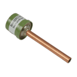
Hydro-Pro - Pressostat haute pression 3,2 MPa / 4,4 MPa (vert) pour pompe à chaleur de type P - 7011008
27,95 €

Hydro-Pro - Pressostat basse pression pour pompe à chaleur 0,3 MPa / 0,15 MPa - 7011009
27,95 €

Flotide/MEGA - Interrupteur de débit d'eau pour pompe à chaleur avec adaptateur à coller de 32 mm - 7006471
51,45 €

Norsup - Échangeur thermique pour les pompes à chaleur P24V/32 et P24TV/32 - 7027693
601,45 €

Norsup - Pale de ventilateur en aluminium Ø 560 mm × 150 mm, rotation antihoraire (alésage de 12,7 mm) - 7027688
157,95 €

Norsup - Fan Speed Control Module 20000-430228 + 35005-310617 - 7027685
195,45 €

Norsup - Carte de commande d'onduleur 2AC32I07WM1 - 7027679
1.093,95 €

Hydro-Pro - Connecteur à 2 voies, blanc, 450 V / 4 mm² - 7011019
4,95 €

Description
Norsup Heat Pump Type PV Inverter (P24V/32) exploded view & spare parts
This page covers the full exploded-view diagram and bill of materials for the Norsup Heat Pump Type PV Inverter, model P24V/32, carried under factory reference 7026969. The diagram breaks the unit down into every major assembly and sub-component — from the refrigerant circuit and electrical cabinet through to the casing panels and water connections. The P24V/32 is a single-phase, vertical-discharge inverter heat pump running on R32 refrigerant, designed for pools up to approximately 125 m³. With 48 numbered positions mapped across the diagram, you should be able to pinpoint the part you need in a matter of minutes.
Comment utiliser le schéma numéroté pour trouver votre pièce
Every call-out number printed on the exploded-view diagram corresponds directly to a numbered row in the parts list below it — locate the area of the unit where your part lives, find its call-out number on the diagram, then read across to the description and SKU in the matching table row. Where a SKU is shown, that part is available to add to your basket directly; where no SKU appears, the component is either only supplied as part of a larger assembly or is not currently available individually. Pay close attention to position 48, which groups several accessory and sensor items together under a single call-out number — read the full description carefully, as each item within that group carries its own separate SKU and product reference. Also note that positions 25 and 26 both describe a conduit bend: the diagram will show two physically separate bends, but they share the same description, so confirm the location on the diagram before ordering to be certain you have the correct one. If you are unsure which position number applies to your part, use the diagram’s section zones — refrigerant circuit, electrical cabinet, fan assembly, and casing — to narrow your search before counting call-outs.
Main replaceable assemblies on the Norsup PV Inverter P24V/32
The fan assembly at the top of the unit centres on position 1, the 200 W ZWS200-B3 fan motor (SKU 7027686), which drives the aluminium fan blade at position 33 — specified as Φ560 mm × 150 mm with a 12.7 mm anti-clockwise bore (SKU 7027688). The blade discharges vertically, making the unit well suited to installations where horizontal clearance is limited. Protecting the fan are the fan net (pos. 34), fan protection plate (pos. 5), and the left, right, and back protection nets (pos. 35 and 31). The refrigerant circuit is anchored by the titanium heat exchanger at position 20, which covers both the P24V/32 and P24TV/32 variants (SKU 7027693), and the compressor SVB220FLGMC-L mounted on its bracket at positions 22 and 21. Refrigerant-side safety is managed by the high-pressure switch at position 6 (3.2 MPa / 4.4 MPa, SKU 7011008) and the low-pressure switch at position 7 (0.3 MPa / 0.15 MPa, SKU 7011009), with an electronic expansion valve (pos. 8) and filter (pos. 9) completing the circuit. The water side is protected by the flow switch at position 12, a 32 mm glue-adapter type (SKU 7006471), which prevents the compressor running without adequate water flow. The electrical cabinet contains the PC1004 PCB controller at position 41 (SKU 7027672), the inverter driver board 2AC32I07WM1 at position 43 (SKU 7027679), the fan speed control module at position 40 (SKU 7027685), and the AC filter plate at position 46 (SKU 7027682). The user interface is the colour display at position 15, factory reference 20000-430176-8200047 (SKU 7024942), mounted behind the front panel at position 14.
Choix entre les différentes variantes et les formats d'emballage
This diagram is specific to the single-phase P24V/32; the closely related P24TV/32 is a three-phase variant that shares certain parts — notably the titanium heat exchanger at position 20 (SKU 7027693), which is listed as compatible with both models — but uses different electrical components, so always confirm your model designation before ordering electrical parts such as the PCB controller (pos. 41) or inverter driver board (pos. 43). The needle valves at positions 10 and 11 are labelled (1) and (2) to distinguish two physically different valves on the refrigerant circuit; order by position number rather than description alone to ensure you receive the correct one. The wire connectors in this unit come in two sizes: the 2-way connector at position 47 (SKU 7011019) and the 5-way connector at position 39 (SKU 7011025) — these are not interchangeable, so match the pole count to your loom before purchasing. Several accessory items listed within position 48 — including temperature sensors, a pressure gauge, Wi-Fi module, and winterisation cover — are available individually under their own SKUs; refer to those separate SKUs rather than to position 48 as a whole when adding these accessories to your order.
