



Vue éclatée et pièces de rechange de la pompe à chaleur Hydro Pro, modèle PX25T/32
 Certifié boutique en ligne
 Retours faciles dans les 14 jours


Liste des pièces de rechange

Hydro-Pro - Écran de commande en verre noir CM404 - 7029494
285,45 €

Hydro-Pro - Pales de ventilateur de rechange 500 mm × 145 mm, alésage de 10 mm, rotation antihoraire (lot de 4) - 7024880
59,95 €

Hydro-Pro - Moteur de ventilateur axial 75 W ZWS75-A - 7024943
315,45 €
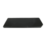
Hydro-Pro - Couvercle supérieur pour pompe à chaleur 1115 x 430 mm (type P marche/arrêt) - 7033048
120,45 €

Hydro-Pro - Pressostat basse pression pour pompe à chaleur 0,3 MPa / 0,15 MPa - 7011009
27,95 €
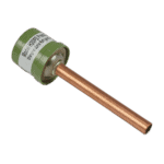
Hydro-Pro - Pressostat haute pression 3,2 MPa / 4,4 MPa (vert) pour pompe à chaleur de type P - 7011008
27,95 €

Flotide/MEGA - Interrupteur de débit d'eau pour pompe à chaleur avec adaptateur à coller de 32 mm - 7006471
51,45 €

Hydro-Pro - Manomètre de réfrigérant à montage sur panneau 0–55 bars R32 - 7026259
44,95 €

Hydro-Pro - Échangeur de chaleur en titane pour les pompes à chaleur P26T/32, P26X/32 et P26TX/32 - 7024878
653,95 €

Hydro-Pro - Carte de commande pour pompe à chaleur P20X/26X série T - 7024941
1.183,95 €

Hydro-Pro - Connecteur à 2 voies, blanc, 450 V / 4 mm² - 7011019
4,95 €

Hydro-Pro - Contrôleur PCB PC1004 pour la pompe à chaleur PIV 25T/32 - 7029491
277,95 €

Hydro-Pro - Carte de commande de fréquence pour les pompes à chaleur P20X / P26X / P35X de la série T - 7025126
398,45 €

Description
Vue éclatée et pièces de rechange de la pompe à chaleur Hydro Pro, modèle PX25T/32
This page provides the official exploded-view diagram and full bill of materials for the Bosta Hydro Pro inverter heat pump Type PX25T/32, listed under Bosta factory reference 7028289. The PX25T/32 is rated at 25 kW and runs on a three-phase 400 V electrical supply, making it one of the larger models in the Hydro Pro inverter range. The Inverter range is designed for year-round use, featuring larger-than-standard heat exchangers and the latest rotary compressor design for effective heating performance throughout its operating range. The diagram covers all 48 numbered positions across the enclosure, refrigeration circuit, fan assembly, water-side components, and electrical box. Use the diagram alongside the parts list below to identify the exact component you need in minutes.
Comment utiliser le schéma numéroté pour trouver votre pièce
Every numbered call-out printed on the exploded-view diagram corresponds directly to a row in the parts list table beneath it — locate your area of the unit first (for example, the fan section, the electrical box, or the water circuit), then find the matching position number on the diagram. Once you have the position number, look it up in the table to read the full part description and, where available, the SKU you need to add to your basket. Bear in mind that some positions in a complex unit like this share a number across more than one physical location — always cross-reference the written description to confirm you are looking at the right component. Position 13 and position 42, for instance, both refer to electrical box sub-assemblies (“Electrical box (1)” and “Electrical box (2)”), so read the descriptions carefully before ordering. Similarly, positions 24 and 25 are both listed as filters (“Filter (1)” and “Filter (2)”), which sit at different points in the refrigeration circuit. Where a position in the BOM carries additional related part numbers in its description — such as position 18, which groups the high pressure switch SKU 7011008 alongside two temperature sensor variants (SKU 7011007 and SKU 7024867) — treat each SKU as a separate orderable item and match it to the sub-description that fits your fault. Not every position has a stocked SKU: where the SKU column is blank, the component is either a structural panel or a refrigerant-circuit part that requires a qualified engineer to source; contact us directly for guidance on those items.
Main replaceable assemblies on the Hydro Pro Heat Pump Type PX25T/32
The fan assembly is one of the most commonly serviced areas: position 4 is the pale de ventilateur (500 mm × 145 mm, 10 mm anticlockwise hole, SKU 7024880) and position 5 is the axial fan motor (75 W, model ZWS75-A, SKU 7024943), both of which are stocked and orderable directly. The fan sits behind a protective net (position 3) and is mounted on a bracket (position 7); the motor is driven by a fan speed control plate at position 48 (SKU 7025129). The electrical box area — covered by the electrical box cover at position 12 — houses several key electronic components: the PC1004 PCB controller for the PIV 25T/32 at position 40 (SKU 7029491), the driver board P20X/26X T-series at position 36 (SKU 7024941), and the frequency controller plate P20X/26X/35X T-series at position 43 (SKU 7025126). The user interface is the glass display CM404 at position 2 (SKU 7029494), mounted on the front panel (position 1). On the refrigeration side, the compressor MVB42FCBMC-L sits at position 32, the détendeur électronique at position 21, and the Vanne à 4 voies à marche arrière at position 27; these components are part of the sealed refrigerant circuit and must be handled by a qualified F-gas engineer. Safety and monitoring of the refrigerant circuit is provided by the low pressure switch 0.3 MPa / 0.15 MPa at position 16 (SKU 7011009), the high pressure switch 3.2 MPa / 4.4 MPa at position 18 (SKU 7011008), and the pressure meter 0–55 bar for R32 refrigerant at position 26 (SKU 7026259). On the water side, the heat exchanger design allows both normal and salt water pools to be heated — this is the titanium heat exchanger PIV 25/32 at position 30 (SKU 7024878) — and water flow is monitored by the commutateur de débit d'eau at position 19 (SKU 7006471). The enclosure itself consists of the front panel (pos. 1), back panel (pos. 9), right panel (pos. 29), top lid 1115 × 430 mm (pos. 11, SKU 7033048), supporting panel (pos. 10), and chassis (pos. 31).
Choix entre les différentes variantes et les formats d'emballage
Position 18 in this BOM bundles three closely related items under one diagram call-out: the high pressure switch (SKU 7011008) and two temperature sensors that differ only in their NTC resistance value — a 5K sensor (SKU 7011007) and a 50K sensor (SKU 7024867). Before ordering a temperature sensor, confirm which value your unit requires by checking the wiring diagram in your service manual, as fitting the wrong resistance rating will cause incorrect temperature readings and may trigger fault codes. Position 48 similarly carries additional accessories within its description, including a 10-metre extension cable and housing (SKU 7029497) and a winter cover (SKU 7025374) alongside the primary fan speed control plate (SKU 7025129) — each of these is a separate product and should be ordered individually using the correct SKU. This is the three-phase 400 V model, so always verify your supply voltage before ordering any electrical component, as single-phase PX25/32 variants use different boards and switches that are not interchangeable with those listed here. Where a position description includes physical dimensions — such as the fan blade at position 4 (500 mm × 145 mm, 10 mm hole) or the top lid at position 11 (1115 × 430 mm) — cross-check those measurements against your existing part before ordering, as even small differences in diameter or fixing-hole size will prevent correct fitment.
