



Pompe à chaleur Flotide/MEGA, type Inverter (référence Xp05Csie) : vue éclatée et pièces de rechange
 Certifié boutique en ligne
 Retours faciles dans les 14 jours


Liste des pièces de rechange

Flotide/MEGA - Capteur de température ambiante TH1 avec connecteur enfichable (6×4) - 7020259
15,95 €
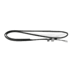
Flotide/MEGA - Capteur de température pour tuyauterie TH2 avec connecteur 6×4 - 7020260
12,45 €

Moteur de ventilateur pour pompe à chaleur de piscine YDK-25-6 25 W - 7010521
92,45 €

Pale de ventilateur pour pompe à chaleur de piscine, 400 mm × 118 mm, alésage de 8 mm, rotation antihoraire - 7010538
31,45 €

Flotide/MEGA - Boîtier d'affichage étanche pour pompe à chaleur à onduleur (type Xp05Csie) - 7010543
31,45 €

Flotide/MEGA - Écran LED pour pompe à chaleur à inverseur SHHCLEDV2MM101 - 7021826
226,95 €

Flotide/MEGA - Panneau d'affichage LED avec Wi-Fi pour pompe à chaleur à onduleur (WiFi02iMM011) - 7023600
252,45 €

Manomètre 0–55 bars R410A - 7010518
47,45 €

Flotide/MEGA - Capteur de température d'entrée d'eau TH6 avec connecteur (6×4) - 7020263
15,95 €

Flotide/MEGA - Échangeur thermique en titane pour la pompe à chaleur Hydro-S Inverter 5 - 7021844
411,95 €

Flotide/MEGA - Bouchon pour tuyau en PP, filetage mâle ½", 10 bars, noir - 0121241
3,45 €

Flotide/MEGA - Capteur de température de sortie d'eau TH5 avec fiche (6×4) - 7020262
15,95 €

Flotide/MEGA - Interrupteur de débit d'eau avec connecteur VH-2 (9 × 7 mm) - 7020257
100,95 €

Flotide/MEGA - Capteur de température des gaz d'échappement TH3 avec connecteur (6×4) - 7020261
15,95 €

Flotide/MEGA - Pressostat haute pression pour pompe à chaleur 3,6–4,2 MPa - 7024793
21,95 €

Flotide/MEGA - Pressostat de basse pression 0,1–0,3 MPa (pompe à chaleur A3/32) - 7024791
21,95 €

Flotide/MEGA - Pressostat de basse pression 0,2–0,35 MPa (pompe à chaleur à onduleur Xp05Csie) - 7024792
21,95 €

Flotide/MEGA - Carte de commande de pompe à chaleur à onduleur SH0150101-V1.5 - 7021834
559,45 €

Condensateur de marche pour moteur, 2 µF, type enfichable à bornes carrées - 7010416
3,45 €

Flotide/MEGA - Courroie de chauffage du carter de compresseur 230 V, 35 W, 340 mm - 7020267
44,45 €

Description
Flotide/MEGA Heat Pump Inverter (Type XP05CSIE) exploded view & spare parts
This page presents the full exploded-view diagram and numbered bill of materials for the Flotide/MEGA Heat Pump, Type Inverter, model reference XP05CSIE (factory assembly reference 7021084). The diagram covers every serviceable component of the unit, from the outer casing panels and air-circuit parts through to the refrigerant circuit, electrical box, and water-side connections. Whether you are a pool owner carrying out routine maintenance or a technician tracking down an exact replacement, the diagram and parts list below will let you identify the component you need and cross it to the correct SKU in minutes. Use the position numbers printed on the diagram as your guide through the sections that follow.
Comment utiliser le schéma numéroté pour trouver votre pièce
Every numbered call-out on the diagram corresponds directly to a row in the parts table below, so begin by locating the area of the unit where you can see the failed or worn component — casing, air circuit, refrigerant circuit, electrical box, or water connections. Once you have found the approximate zone, scan that area of the diagram for the relevant position number, then match that number to the same row in the table to retrieve the SKU for ordering. Bear in mind that some position numbers share the same SKU — for instance, positions 40 and 41 are both listed as Water Connection Set (SKU 7014153), because the inlet and outlet fittings are identical parts supplied from the same stock code; order one SKU per fitting you need to replace. Also note that position 28 carries two lettered variants: 28a is the LED Display Inverter SHHCLEDV2MM101 (SKU 7021826) and 28b is the LED Display Inverter WiFi02iMM011 (SKU 7023600), reflecting two different display board options fitted across the production run — confirm which variant is installed in your unit before ordering. Where a position number has no SKU shown, that part is not currently stocked as a separate line item; please contact us for guidance if you need one of those components. Similarly, two positions are both simply labelled “Clip” (positions 7 and 25) — identify which clip by its location on the diagram rather than its description alone.
Main replaceable assemblies on the Flotide/MEGA Heat Pump Inverter (Type XP05CSIE)
The unit is best understood as five interconnected sub-assemblies. The outer casing consists of the top cover (pos. 1), front panel (pos. 15), left panel (pos. 11), right panel (pos. 23), back panel (pos. 33), back grill (pos. 4), ventilation grid (pos. 16), and maintenance panel (pos. 17); these protect the internal components and direct airflow through the evaporator. The air circuit centres on the evaporator (pos. 10), the fan motor YDK-25-6 25 W (pos. 13, SKU 7010521), and the fan blade 400 mm × 118 mm with 8 mm anticlockwise bore (pos. 14, SKU 7010538), all mounted via the fan motor bracket (pos. 12) and supported by anti-vibration hammers (pos. 18) to minimise noise and vibration. The circuit de réfrigérant is made up of the compressor (pos. 19), 4-way valve (pos. 46), electronic expansion valve (pos. 54), high-pressure switch rated 3.6–4.2 MPa (pos. 49, SKU 7024793), low-pressure switches at 0.1–0.3 MPa (pos. 50, SKU 7024791) and 0.2–0.35 MPa (pos. 55, SKU 7024792), the suction valve (pos. 52), reactor/PFC conductor (pos. 30), and a pressure gauge for system monitoring (pos. 29, SKU 7010518); associated pipework spans positions 31, 32, 48, 51, 53, 56, 57, and 58. The circuit d'eau is served by the titanium heat exchanger (pos. 36, SKU 7021844), water flow switch VH-2 (pos. 45, SKU 7020257), and four plug-type temperature sensors: ambient TH1 (pos. 2, SKU 7020259), pipe TH2 (pos. 6, SKU 7020260), exhaust TH3 (pos. 47, SKU 7020261), water-out TH5 (pos. 44, SKU 7020262), and water-in TH6 (pos. 34, SKU 7020263); the water connections are made up via matched water connection sets at positions 40 and 41 (both SKU 7014153) together with sealing rings at positions 38, 39, 42, and 43 and an ½″ male-thread PP plug (pos. 37, SKU 0121241). The coffret électrique (pos. 64) houses the main PC board SH0150101-V1.5 (pos. 60, SKU 7021834), capacitor 2 µF square-plug type (pos. 61, SKU 7010416), magnetic rings (pos. 62, 63), 5-seat terminal (pos. 24), terminal panel (pos. 22), cable connector (pos. 21), and is completed by the electric box cover (pos. 59); the waterproof display box (pos. 27, SKU 7010543) and the chosen LED display board at position 28 mount externally to this assembly. Finally, the compressor heating belt 230 V 35 W 340 mm (pos. 65, SKU 7020267) wraps the compressor to prevent refrigerant migration during cold-start conditions.
Choix entre les différentes variantes et les formats d'emballage
The most important variant choice on this model is the LED display board at position 28. Position 28a (SKU 7021826, SHHCLEDV2MM101) is the standard inverter display, while position 28b (SKU 7023600, WiFi02iMM011) is the Wi-Fi-enabled version; fitting the wrong board will result in an incompatible connector or missing firmware functionality, so open the waterproof display box (pos. 27) and read the label on the existing board before ordering. For the water connection sets at positions 40 and 41 (both SKU 7014153), both positions draw from the same part, but each physical fitting is a separate unit — order two if you are replacing both the inlet and outlet sides at the same time. The four temperature sensors at positions 2, 6, 34, 44, and 47 all share the same 6×4 plug format and are listed under individual SKUs tied to their specific measurement point (ambient, pipe, water-in, water-out, exhaust); although the plug bodies look similar, each sensor is calibrated for its location in the circuit, so always order by position number rather than plug size alone. Similarly, the two low-pressure switches at positions 50 and 55 carry different rated pressure ranges (0.1–0.3 MPa and 0.2–0.35 MPa respectively) and must not be interchanged, even though they may appear physically identical on the bench.
