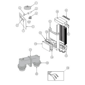
EcoSalt Chlorinator (Last Sold 2017, MES series) exploded view & spare parts
 Certificado tienda en línea
 Devoluciones fáciles dentro de 14 días


Lista de piezas de repuesto

Davey - EcoSalt 13 Replacement Transformer - M1731
141,95 €
Davey - EcoSalt 20 Chlorinator Transformer (Power Supply) - M1732
157,95 €
Davey - Transformador de recambio para EcoSalt 26 / BMSC 26 - M1733
190,45 €
Davey - ProMatic Salt Chlorinator Controller Fuse 3A (MPS16 / MPS24) - M2901
3,95 €
Davey - EcoSalt BMSC 13 Main Control PCB (Electronic Board) - M112013EUSP
348,95 €
Davey - EcoSalt 20 Replacement Electronic PCB (Controller Board) - M112020EUSP
352,45 €
Davey - EcoSalt 26 Main Control PCB (While Stock Lasts) - M112026EUSP
359,95 €
Davey - Cable de células EcoSalt BMSC – Célula en forma de U (todos los modelos BMSC) - M2678
93,95 €
Davey - EcoSalt BMSC-MES U-Shape Cell Union Ring - M8228
15,45 €
Davey - Racor de unión celular en forma de U EcoSalt de 63 mm (Europa) - M8229E
15,95 €
Davey - Conector celular EcoSalt en forma de U de 60 mm - M8229
16,45 €

Descripción
Davey EcoSalt Chlorinator (MES series) exploded view & spare parts
This page covers the complete exploded-view diagram and parts list for the Davey EcoSalt MES-series salt-water chlorinator, sold under factory references MES13CE y MES20CE. The diagram also references components shared with the MES26 variant, so owners of that model will find relevant parts here too. The MES series was last manufactured in 2017 and comprised three output tiers — 13 g/h, 20 g/h, and 26 g/h — each sharing a common housing design but using model-specific internal components such as the transformer, PCB, and electrolytic cell. Work through the numbered diagram below and you will be able to match your failed or worn part to its SKU in a matter of minutes.
Cómo utilizar el esquema numerado para localizar tu pieza
Every circled or arrowed number in the diagram corresponds directly to a position number (pos) in the parts table beneath it — locate the area of the unit that concerns you, note the position number, then look up that row in the table to find the correct SKU to add to your basket. Begin by identifying the broad area of the chlorinator that has failed: the control housing, the cell body, or the plumbing unions, then drill down to the specific position number within that area. Pay close attention to positions where the same number appears more than once in the table — positions 1 (Transformer), 5 (PCB), 17 (Cell), and 20 (Union Head) each carry multiple SKUs that correspond to different model sizes or pipe dimensions; selecting the wrong one will result in a part that does not fit or perform correctly. For those multi-variant positions, confirm your model designation (MES13, MES20, or MES26) from the label on the side of the electrical panel before choosing. Where a position lists a single SKU — such as position 2 (Fuse Holder, M2953) or position 6 (Power Switch, M2004) — that part is common across all three output sizes, so no additional selection is required. If a position number appears physically more than once in the diagram (for example, a fastener used at several points on the housing), the single SKU covers all instances of that fastener in the unit.
Main replaceable assemblies on the Davey EcoSalt MES series
The MES-series chlorinator divides naturally into three functional areas: the electronics housing, the cell assembly, and the plumbing interface. Within the electronics housing, position 1 holds the Transformer — the heaviest and often first component to show age-related failure; there is a dedicated SKU for each output size (M1731 for MES13, M1732 for MES20, M1733 for MES26). Closely associated with the transformer is the fuse circuit: position 2 (Fuse Holder, M2953) and position 3 (Fuse 3 Amp, M2901) are the first items to inspect if the unit trips or fails to power on. Position 4 is the Filter (14756PG), which protects the electronics from mains-borne interference and is a common oversight during servicing. The main control logic lives on the PCB at position 5, again model-specific (M112013EUSP, M112020EUSP, or M112026EUSP), with the operator-facing controls immediately adjacent: position 6 the Power Switch (M2004) and position 7 the Chlorine Control Knob (M1521). The housing shell itself is represented by positions 8 through 16, covering the Top Baffle, Rear Bracket, Top Cover, Front Cover, Base, Door, Decal Housing, and both door linkage mechanisms (swinging at position 15, sliding at position 16) — useful when replacing cracked or UV-degraded panels. The electrolytic cell at position 17 is the consumable heart of the system; the cell is the component responsible for generating disinfectant, and over time its plates wear and chlorine output declines. The Cell Lead Assembly at position 18 (M2678) connects the cell to the PCB and should be inspected whenever a cell is replaced. Positions 19 y 20 cover the plumbing union — the Union Nut (M8228) and the Union Head — which seal the cell body into the pipe run.
Choosing between variants and pack sizes
The most critical variant decision on this diagram concerns the four positions that carry model-specific parts: always cross-reference your unit’s label against the MES13, MES20, or MES26 designation before ordering a Transformer (pos 1), PCB (pos 5), or Cell (pos 17). Each output model is independent — it is not possible to fit a cell from one output size to a different model, because the voltage applied to each varies. Position 20 (Union Head) presents a dimensional variant unrelated to output size: SKU M8229E suits a 63 mm internal diameter Euro pipe fitting, while M8229 suits a 60 mm internal diameter fitting — measure your existing pipework or union before ordering, as the two are not interchangeable. Where the BOM lists a single SKU for a position (such as the Fuse 3 Amp at pos 3 or the Power Switch at pos 6), that part fits all three output variants without modification, simplifying your order. Always order fuses and small consumables such as pos 3 in sufficient quantity for a working spare, as combining a service visit with a single fuse replacement is a common cause of unnecessary callbacks.